In a few prior posts, I mentioned that I replaced the soundproof cabinet's exhaust fans with quieter ones and added a temperature controller for the fans' speed. I sized the new fans well...much quieter, and they can handle the steady state heat extraction when the cluster is running at full power. However, what I didn't account for was heating of the room. The cluster is in a small office, and the office heats up after a few hours at full power. This makes sense...it's thermally equivalent to leaving a 1500W space heater on for hours/days. The reason that's a problem is that the inlet air is now hotter, which causes the exhaust to be even hotter, which causes the inlet air to be hotter, etc. The cabinet has a barrier between the outlet and inlet (both on the bottom of the cabinet) to minimize re-circulation, but if the whole room is hot, that doesn't matter. Leaving the door fully open and putting a large fan in the doorway seems to help some. It also offsets the house's gas heating needs, especially for the upper floor (where the office is). However, it's still getting too hot inside the room and cabinet. I don't have a great solution for this yet...
To do:
1. Fix room heating problem
2. Replace ntpd with chronyd
Sunday, November 18, 2018
Friday, November 16, 2018
Automatic mulit-threading with python numpy
This came up while running python codes on the cluster. It turns out that numpy vector operations are automatically parallelized if numpy is linked against certain libraries, e.g. openBLAS or MKL, during compilation. Those linear algebra libraries will automatically use the max number of available cores (or if your processor is HT, 2x number of physical cores) for matrix operations. While that might seem convenient, it actually made a lot of people unhappy because of the overhead involved with multithreading lots of tiny matrix operations. Fortunately, there is a way to control the max number of threads used, and some devs are working on a way of dynamic control via numpy.
I created the following basic test script. It generates two random matrices, then multiplies them together. The random number generation is a serial operation, but the dot product is parallelized by default.
I ran some experiments on one of the compute nodes (dual e5-2690v2) using slurm execution. Software was anaconda 5.2, so anyone with a recent anaconda should have similar behavior. My np.show_config() returned information about MKL and openBLAS, so I think those are the relevant variables to set.
Test 1: slurm cpus-per-task not set, ntasks=1, no thread limiting variables set.
Results: No multi-threading because slurm defaults to one cpu per task.
Test 2: slurm cpus-per-task=10, ntasks=1, no thread limiting variable set.
Results: dot used 10 threads (10.4s)
Test 3: slurm cpus-per-task=20, ntasks=1, no thread limiting variable set.
Results: dot used 20 threads (5.4s)
Test 4: slurm cpus-per-task=4, ntasks=1, no thread limiting variable set.
Results: dot used 4 threads (24.8s)
Test 5: slurm cpus-per-task=10, ntasks=1, ntasks-per-socket=1, OMP_NUM_THREADS=4
Results: dot used 4 threads (24.8s)
Test 6: slurm cpus-per-task=10, ntasks=1, ntasks-per-socket=1, OPENBLAS_NUM_THREADS=4
Results: dot used 10 threads (10.4s)
Test 7: slurm cpus-per-task=10, ntasks=1, ntasks-per-socket=1, MKL_NUM_THREADS=4
Results: dot used 4 threads (24.9s)
Test 8: slurm cpus-per-task=10, ntasks=1, ntasks-per-socket=1, VECLIB_MAXIMUM_THREADS=4
Results: dot used 10 threads (10.4s)
Test 9: slurm cpus-per-task=10, ntasks=1, ntasks-per-socket=1, NUMEXPR_NUM_THREADS=4
Results: dot used 10 threads (10.4s)
Test 10: slurm cpus-per-task=10, ntasks=1, ntasks-per-socket=1, OMP_NUM_THREADS=8, OPENBLAS_NUM_THREADS=8, MKL_NUM_THREADS=8
Results: dot used 8 threads (12.5s)
As you can see above, setting either MKL or OMP_NUM_THREADS will limit the number of threads, though apparently openBLAS is not being used, at least for dot. Also, limiting the number of cpus available will also limit the number of threads.
For this code, which has to run on 100's of different cases that can be run simultaneously, it looks like giving one full socket per case (10 cores) is optimal. The environment variables don't need to be set because the default behavior is to use all available cores (limited by slurm). That's assuming np.dot is a good indicator, which it might not be because her code is far more complicated.
Anyways, I hope someone finds this useful.
I created the following basic test script. It generates two random matrices, then multiplies them together. The random number generation is a serial operation, but the dot product is parallelized by default.
import osThe lines under import os set environment variables. The one(s) you need to set depend on what your numpy is linked against, as shown by np.show_config(). Note that those must be set before importing numpy.
#must set these before loading numpy:
os.environ["OMP_NUM_THREADS"] = '8' # export OMP_NUM_THREADS=4
os.environ["OPENBLAS_NUM_THREADS"] = '8' # export OPENBLAS_NUM_THREADS=4
os.environ["MKL_NUM_THREADS"] = '8' # export MKL_NUM_THREADS=6
#os.environ["VECLIB_MAXIMUM_THREADS"] = '4' # export VECLIB_MAXIMUM_THREADS=4
#os.environ["NUMEXPR_NUM_THREADS"] = '4' # export NUMEXPR_NUM_THREADS=6
import numpy as np
import time
#np.__config__.show() #looks like I have MKL and blas
np.show_config()
start_time=time.time()
#test script:
a = np.random.randn(5000, 50000)
b = np.random.randn(50000, 5000)
ran_time=time.time()-start_time
print("time to complete random matrix generation was %s seconds" % ran_time)
np.dot(a, b) #this line should be multi-threaded
print("time to complete dot was %s seconds" % (time.time() - start_time - ran_time))
I ran some experiments on one of the compute nodes (dual e5-2690v2) using slurm execution. Software was anaconda 5.2, so anyone with a recent anaconda should have similar behavior. My np.show_config() returned information about MKL and openBLAS, so I think those are the relevant variables to set.
Test 1: slurm cpus-per-task not set, ntasks=1, no thread limiting variables set.
Results: No multi-threading because slurm defaults to one cpu per task.
Test 2: slurm cpus-per-task=10, ntasks=1, no thread limiting variable set.
Results: dot used 10 threads (10.4s)
Test 3: slurm cpus-per-task=20, ntasks=1, no thread limiting variable set.
Results: dot used 20 threads (5.4s)
Test 4: slurm cpus-per-task=4, ntasks=1, no thread limiting variable set.
Results: dot used 4 threads (24.8s)
Test 5: slurm cpus-per-task=10, ntasks=1, ntasks-per-socket=1, OMP_NUM_THREADS=4
Results: dot used 4 threads (24.8s)
Test 6: slurm cpus-per-task=10, ntasks=1, ntasks-per-socket=1, OPENBLAS_NUM_THREADS=4
Results: dot used 10 threads (10.4s)
Test 7: slurm cpus-per-task=10, ntasks=1, ntasks-per-socket=1, MKL_NUM_THREADS=4
Results: dot used 4 threads (24.9s)
Test 8: slurm cpus-per-task=10, ntasks=1, ntasks-per-socket=1, VECLIB_MAXIMUM_THREADS=4
Results: dot used 10 threads (10.4s)
Test 9: slurm cpus-per-task=10, ntasks=1, ntasks-per-socket=1, NUMEXPR_NUM_THREADS=4
Results: dot used 10 threads (10.4s)
Test 10: slurm cpus-per-task=10, ntasks=1, ntasks-per-socket=1, OMP_NUM_THREADS=8, OPENBLAS_NUM_THREADS=8, MKL_NUM_THREADS=8
Results: dot used 8 threads (12.5s)
As you can see above, setting either MKL or OMP_NUM_THREADS will limit the number of threads, though apparently openBLAS is not being used, at least for dot. Also, limiting the number of cpus available will also limit the number of threads.
For this code, which has to run on 100's of different cases that can be run simultaneously, it looks like giving one full socket per case (10 cores) is optimal. The environment variables don't need to be set because the default behavior is to use all available cores (limited by slurm). That's assuming np.dot is a good indicator, which it might not be because her code is far more complicated.
Anyways, I hope someone finds this useful.
Saturday, November 3, 2018
Homelab Cluster: Hardware Finally Done
The day has finally come: I'm happy with the homelab's hardware. *fireworks*
Final list of hardware:
1. Headnode: ASUS Z10PE-D8, 2x Xeon E5-2690V4 ES (14c @ 3GHz), 8x8GB 2Rx8 PC4-19200 ECC RDIMMs, 500GB Samsung 960 Evo NVMe (CentOS 7.5), 2x 3TB HDD in RAID1 (data), 480GB SSD (Windows), GTX Titan, CX354A FDR IB HCA.
2. Compute nodes: Supermicro 6027TR-HTR, which has 4x nodes: 2x E5-2690v2, 8x8GB dual rank PC3-14900R ECC RDIMMs, 120GB SSD (CentOS 7.5 compute node), CX354A FDR IB HCA.
3. Mellanox SX6005 FDR switch with Sonoff wifi power switch
4. 2x 8 port unmanaged 1Gbe switches, one for IPMI, one for intranet
5. Riello UPS: 3300VA, 2300W
6. APC NetShelter CX Soundproof Cabinet with custom, automatic heat extraction system
Here are some pictures:
 The whole homelab + 3D printer. It's final position will be about 2 feet to the right. The plywood under it is to allow for easy rolling over the carpeted floor. My desk with the monitor is just to the right.

Front of cabinet. Looks clean and organized.
 Back is a little bit of a mess, but it's the best I could come up with. All of the cables are too long, so I had to coil them.

Close up of heat extraction electronics. The controller board is mounted in its new 3D printed tray.
It's currently cranking through TB's of astrophysics data. I'll be running CFD cases on it soon.
2. Rack rails/strips. Racking the server and switches might help clean up the wiring inside slightly and make it look neater. The biggest problem with doing this is that I will lose the ability to pull the SM compute nodes out. They come out of the back, and I currently have to slide the server to the side/angle it so that I can pull a node out of the back door. If the server chassis is racked, I won't be able to do that, so I'd have to pull the whole chassis out in order to get to a node. Aside from make it look a little prettier, adding rack rails would be pretty pointless, so this probably won't happen.
3. AMD EPYC. The new AMD EPYC processors are awesome for CFD. Each has 8 channels of DDR4-2666 RAM = crazy high memory bandwidth = more tasks/CPU before hitting the memory bandwidth bottleneck. Looking at the OpenFOAM benchmarks, two dual 7301 servers with dual rank RAM (4 CPUS, 64 cores @~2.9GHz) should be faster than my entire cluster (10 CPUS, 108 cores @~3GHz), and it's almost all thanks to memory bandwidth. Unfortunately, the economics don't make any sense. Building just one dual socket 7301 server/workstation would cost more than I spent on this whole cluster, even if the RAM, CPUs, and motherboard were all purchased used. Because its new hardware, there aren't many used EPYCs or motherboards on the market yet. Also, DDR4 RAM is absurdly expensive, mostly due to price fixing/collusion between the only three RAM manufacturers in the world. Two dual socket EPYC servers would require 32x dual rank 2666 RAM, which for 8GB at the cheapest (new) prices I could find would run about ~$3500....ouch. Again, since that's the latest speed RAM, there isn't much pre-owned DDR4-2666 yet. I did an electricity price analysis to see if it would still make sense economically to upgrade. Assuming running for 1/2 of a year, the current server would use 6100 kWh. At $0.22/kWh (England...), that's about $1350/year in electricity. I think two AMD EPYC servers would use about 900W. That's about $870/year in electricity, for a savings of ~$480/year. Even including selling off what I currently have, it'd take more years than it's worth for me to break even. So if/when this upgrade occurs, it will be in the future when the prices come down. One really exciting prospect of the EPYC chips is that they allow overlclocking. The famous overclocker der8auer's EPYC build used a prototype Elmor Labs to EVC v2 to overclock dual 7601's to 4GHz (all cores) on a Supermicro H11DSI and an ASUS RS700a-e9. He had to use novec submersion or dry ice, but he was able to get a fairly good overclock with a water cooler. Overclocking doesn't make sense in a large cluster/data center environment where running costs (electricity, cooling, maintenance) dominate. Power (and thus heat) scales with frequency cubed, so it's cheaper for them to buy more servers and not overclock. But in a homelab/small cluster environment, where initial hardware costs are usually the dominating factor, overlcocking makes a lot of sense, so this might be something I look into in a few years.
4. Add internal LED lights that come on when either the front or back doors are opened. These would probably be in the form of stick-on strips along the top front and top rear of the cabinet running off of the heat extraction system PSU. The only reason I haven't done this is that I doubt I'll be opening the cabinet much anymore now that everything is situated, heat extraction is automatic, and powering on equipment can all be done remotely.
Final list of hardware:
1. Headnode: ASUS Z10PE-D8, 2x Xeon E5-2690V4 ES (14c @ 3GHz), 8x8GB 2Rx8 PC4-19200 ECC RDIMMs, 500GB Samsung 960 Evo NVMe (CentOS 7.5), 2x 3TB HDD in RAID1 (data), 480GB SSD (Windows), GTX Titan, CX354A FDR IB HCA.
2. Compute nodes: Supermicro 6027TR-HTR, which has 4x nodes: 2x E5-2690v2, 8x8GB dual rank PC3-14900R ECC RDIMMs, 120GB SSD (CentOS 7.5 compute node), CX354A FDR IB HCA.
3. Mellanox SX6005 FDR switch with Sonoff wifi power switch
4. 2x 8 port unmanaged 1Gbe switches, one for IPMI, one for intranet
5. Riello UPS: 3300VA, 2300W
6. APC NetShelter CX Soundproof Cabinet with custom, automatic heat extraction system
Here are some pictures:


Front of cabinet. Looks clean and organized.


Close up of heat extraction electronics. The controller board is mounted in its new 3D printed tray.
 |
| Mounted power strip for not-C13-plug things |
Possible future changes
Since I just got finished saying that the homelab cluster is finished, it's time to list some possible future upgrades, because that's how this hobby goes...
1. Clean up the wiring a little more. It's kind of ugly in the back due to all of the coiled up wires. I'm not really sure how to make it neater without custom cables, though, and that definitely isn't worth the time/money involved to me.
3. AMD EPYC. The new AMD EPYC processors are awesome for CFD. Each has 8 channels of DDR4-2666 RAM = crazy high memory bandwidth = more tasks/CPU before hitting the memory bandwidth bottleneck. Looking at the OpenFOAM benchmarks, two dual 7301 servers with dual rank RAM (4 CPUS, 64 cores @~2.9GHz) should be faster than my entire cluster (10 CPUS, 108 cores @~3GHz), and it's almost all thanks to memory bandwidth. Unfortunately, the economics don't make any sense. Building just one dual socket 7301 server/workstation would cost more than I spent on this whole cluster, even if the RAM, CPUs, and motherboard were all purchased used. Because its new hardware, there aren't many used EPYCs or motherboards on the market yet. Also, DDR4 RAM is absurdly expensive, mostly due to price fixing/collusion between the only three RAM manufacturers in the world. Two dual socket EPYC servers would require 32x dual rank 2666 RAM, which for 8GB at the cheapest (new) prices I could find would run about ~$3500....ouch. Again, since that's the latest speed RAM, there isn't much pre-owned DDR4-2666 yet. I did an electricity price analysis to see if it would still make sense economically to upgrade. Assuming running for 1/2 of a year, the current server would use 6100 kWh. At $0.22/kWh (England...), that's about $1350/year in electricity. I think two AMD EPYC servers would use about 900W. That's about $870/year in electricity, for a savings of ~$480/year. Even including selling off what I currently have, it'd take more years than it's worth for me to break even. So if/when this upgrade occurs, it will be in the future when the prices come down. One really exciting prospect of the EPYC chips is that they allow overlclocking. The famous overclocker der8auer's EPYC build used a prototype Elmor Labs to EVC v2 to overclock dual 7601's to 4GHz (all cores) on a Supermicro H11DSI and an ASUS RS700a-e9. He had to use novec submersion or dry ice, but he was able to get a fairly good overclock with a water cooler. Overclocking doesn't make sense in a large cluster/data center environment where running costs (electricity, cooling, maintenance) dominate. Power (and thus heat) scales with frequency cubed, so it's cheaper for them to buy more servers and not overclock. But in a homelab/small cluster environment, where initial hardware costs are usually the dominating factor, overlcocking makes a lot of sense, so this might be something I look into in a few years.
4. Add internal LED lights that come on when either the front or back doors are opened. These would probably be in the form of stick-on strips along the top front and top rear of the cabinet running off of the heat extraction system PSU. The only reason I haven't done this is that I doubt I'll be opening the cabinet much anymore now that everything is situated, heat extraction is automatic, and powering on equipment can all be done remotely.
Thursday, November 1, 2018
Review of Cheap Fan Temperature PWM Controllers
I purchased a couple more types of cheap (~$5) temperature fan controllers from eBay. There are about 5 or so different types. Since I reviewed one previously, and I now own three of the most common ones, I thought I'd do a review of all of them in one place.
First, a brief review of standard fan control methods. There is a lot of confusing terminology out there regarding small dc fan control. 2 pin fans just have power and ground. These can be controlled either by varying voltage linearly, or by PWM'ing the power line. The former only works down to ~half the rated voltage for most fans or they don't have enough power to start. The latter requires a PWM fan controller. 3 pin fans have an extra wire that outputs the tachometer readings. This is useful for measuring fan speed if the power source is constant, i.e. not PWM'd. If the power is PWM'd, then the sensor is, too, which usually messes up its readings, unless the PWM frequency is much greater than the RPM. 4 pin fans have power, gnd, tach, and control wires. In addition to the two methods mentioned for two pin fans, these have a third option for control. In stead of PWM'ing the power wire, a low voltage/low current PWM signal can be sent to the control wire. The fan's internal electronics then handle the actual power PWM'ing. This has the added benefit of not screwing up the tach sensor readings because the voltage on the power wire is still consistent. Unfortunately, finding a cheap controller for these fans is difficult. Noctura makes a ~$20 manual pot one, but that's the only one I could find. I'm reviewing the three most common cheap chinese eBay ones here.
Fan Controller 1

This is the controller I reviewed in March. It can handle two fans of 2, 3 or 4 pins in 2-pin control mode. 12-24V input, max 4A output. It will automatically adjust the two fan outputs' duty cycle based on the reading from a temperature probe.
The control chip is a TC648 dedicated fan temperature controller. Unfortunately, the PWM switching frequency is about 30 Hz, and is audible/visible and annoying. If the switch is up, the potentiometer allows for tuning the turn-on temperature, which is nominally 30C, and always about 20C lower than the max temperature, nominally 50C. The pot is very sensitive. If the switch is down, supposedly the temperature set points are fixed at 30C and 50C, but I don't think they're accurate. At 12V, the acceleration is smooth, but very slow. At 24V, the acceleration in the control band is underdamped, so the fan speed oscillates wildly. Note that the 2A or 3A versions have one missing FET (like the one pictured), but the 4A one has all of them. Because this one pulses the power pin, there is a voltage drop across the board that results in the fan not operating at the same maximum RPM as if it was plugged directly into the power supply.
Conclusion: Not recommended.
Fan Controller 2
 This controller only works with 12V 4 pin fans operating in 4-pin control mode. Each of the three fans has a max operating current of 3A. It should be possible to splice a wire from the 12V input line to the fan's 12V cable in order to have a higher than 3A current limit. It will automatically adjust FAN1's PWM (control pin, not the power pin) duty cycle based on the temperature read by the short temperature probe. FAN2 and FAN3 are only controlled manually by the two potentiometers. FAN2 and FAN3's minimum duty cycle is 10%. There is a stalled fan warning beeper. There are 5 DIP switches. Switch 1 controls the minimum duty cycle of FAN1, either 20% or 40%. Switches 2 and 3 allow for the selection of one of four minimum and maximum temperature pairs: 35C-45C, 40C-55C, 50C-70C, 60C-90C. Switches 4 and 5 control the behavior of the stall alarm for FAN1 and FAN2. All fans will always be on: there is not automatic shutoff. The chip is not marked, but it must be some sort of microcontroller. Come to think of it, a simple microcontroller will probably be cheaper than a chip specifically designed for fan temperature control because more microcontrollers are produced than fan control chips.
The temperature control works fairly well: acceleration is smooth in the control band. The pot controlled fans are adjustable from about 10-100% duty cycle. It reaches the same max RPM as if the fan was directly connected to a 12V source. Board current consumption is very low, a few 10's of mA.
Conclusion: If you have 12V 4-pin fan(s), and one of those temperature ranges works for you, and especially if you need to manually set two other fans as well, then this is a good pwm fan temperature controller for you.
Fan Controller 3
 This controller works with 12-60V 4 pin fans operating in 4-pin control mode. Each of the two fans has a max operating current of 3A. It should be possible to splice a wire from the power input line to the fan's power cable in order to have a higher than 3A current limit. It will automatically adjust FAN1's PWM (control pin, not the power pin) duty cycle based on the temperature read by the long (~1m) temperature probe 1, and the same for FAN2 and temperature probe 2. In other words, it has two separate control zones, which is nice. The low and high temperature ranges are settable from 0-60C and 10-70C respectively, in 1C increments.The interface is the best out of all of them: buttons for selecting modes and changing settings, and a 3 digit 8 segment display, along with 4 indicator LEDs for displaying the current settings, temperatures, and fan RPMs. The temperature probes are long and potted in metal tubes. It has a stall alarm for both fan outputs. Fan minimum duty cycle is adjustable between 10-100% in increments of 1%, which can be used to manually control the fans if the minimum start temperature is set higher than ambient. This one is a bit larger than the other boards, and current consumption is about 40mA. Fans are always on: not auto-shutoff feature. The two chips near the top are shift registers (74hc595d) for the 8 segment displays and the LEDs. The chip near the capacitor is a buck converter (xl7005a) for powering the board, and the chip on bottom left is a microcontroller (N76e003At20).
It works great. Acceleration is silky smooth from the low temperature set point to the high temperature set point. It reaches the same max RPM as if the fan was directly connected to the power source. Acceleration is a little slow, likely because of the potted temperature probes taking a long time to heat up. It's faster than Fan Controller 1, though. I haven't tried this with voltages other than 12V input, but my guess is the behavior would be the same due to the buck converter.
Conclusion: This board is awesome. If you need to do temperature control, especially dual zone, of 4-pin fans of 12-60V, then this is the board for you. I will be using this in my homelab's cabinet to control the heat extraction fans. The only feature I wish it had was automatic stop/start of the fans so they wouldn't run when below the min temperature threshold.
Fan Controller 4
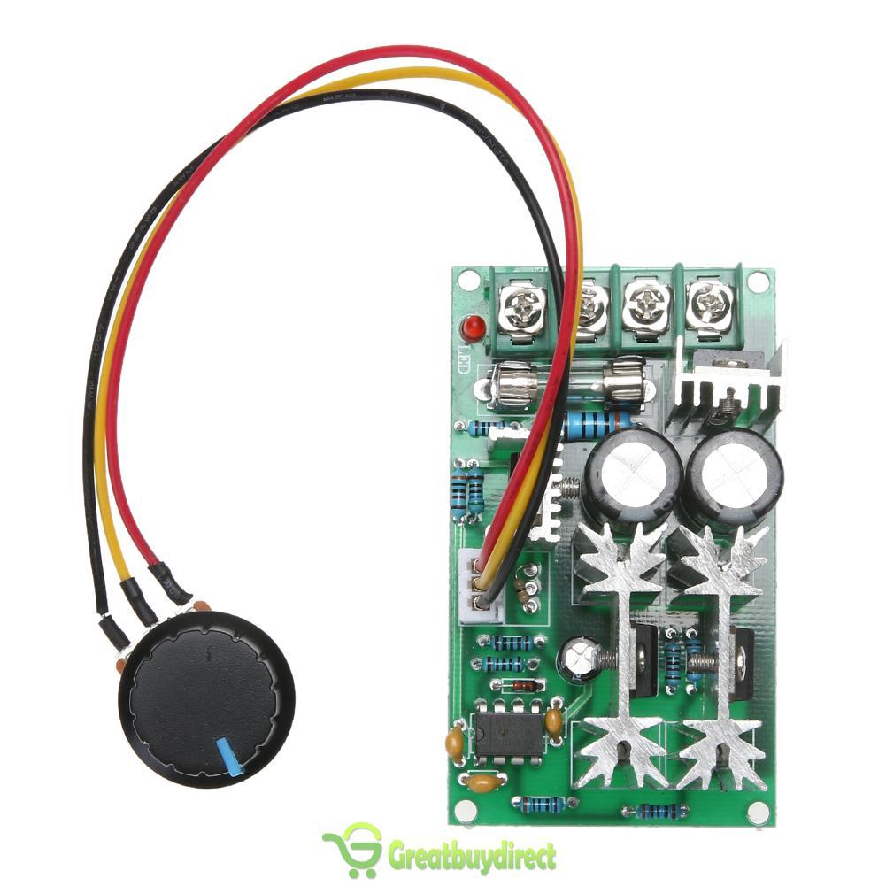 This controller is not a temperature controller, but a manual PWM controller. The PWM duty cycle (power is PWM'd, so this would be 2-pin fan mode) is controlled by the potentiometer. It has one output, and is supposedly rated for up to 60V and 20A, though considering how hot it gets with just a few amps, I'm not sure I'd want to push 20 through it. On 12V, as you turn the pot, the output is fairly smooth, but with 24V, only the first ~3% of the pot can be used to change RPM, the rest is full speed. The PWM frequency is high enough not to hear or notice, unlike Fan Controller 1, so that's good. It works, so if you just need manual fan control of 2 or 3 pin fans, especially high power ones, then this is a good choice for you.
Hopefully this review will help someone in the future choose a PWM fan temperature controller.
As I mentioned above, I will be using Fan Controller 3 moving forward. I had to create a new wiring harness.

I'm using FAN1's output to control all three fans. Because their total current is greater than 3A (limit of a fan connector), I had to run bypass pwr and gnd wires directly to the power supply. I pulled the pwr pin from the 4-pin fan connector that plugs into the controller to prevent current from being run through the connector. I also soldered small power wires for the controller to the fork terminals on the bypass wires. The three PWM control pins are wired together in the harness to the single blue wire connected to the controller, but only one of the yellow tachometer wires is so the tach signals don't mix. I 3D printed some terminal covers for the power supply because it didn't come with any. I'm going to 3D print a green tray to hold the controller PCB and to shield its back from shorting. I'll set the set points to 30C-40C, and the temperature probe will be taped to the top back of the cabinet. If that part of the cabinet gets to about 30C, then the heat extraction fans aren't moving enough air to prevent hot air from recirculating to the front of the servers, so they need to ramp up.
When I was testing Fan Controller 3, I noticed that the 10% duty cycle command only corresponded to 50% of the max fan RPM and the 100% duty cycle corresponded to max fan RPM. At first, I thought something might be wrong with the controller, but measuring the average DC voltage of the PWM control pin showed that it, at 10% duty cycle setting, was reaching about 12% of the voltage at max duty cycle duty cycle setting, so that meant the controller was probably fine. Unfortunately, Mechatronics, the manufacturer of the fans I purchased, does not publish PWM vs. RPM data. I found digging through their website that 50% is the minimum fan RPM, which is what I observed earlier. It's unfortunate that those fans don't allow for lower RPM operation. I measured operating current and found that at the lowest setting, the fan draws 19% of the power it does at max RPM, which is a savings of ~35W for all three fans. It'd be nice if the fan controller could turn the fans off, but that'd only save an additional ~8W. Compared to leaving them running at full speed all of the time, I'm probably saving somewhere around $30/year (assuming the fans are at min throttle half of the year) by implementing fan temperature control.
On a separate note, I tried installing a second fan on the CPU cooler on CPU1 in the headnode. The Cooler Master Hyper 212 Evo's come with an extra pair of brackets for mounting a second 120mm fan on the other side of the heatsink. The 120mm fans and y splitters I bought were 3 pin, though, instead of 4-pin, which means that both fans ran at 100%. It'd have been better to buy another 4-pin fan and a 4-pin splitter cable so that they could be throttled with load. I realized that full speed was a lot faster than I had seen the fan spin before. I did a stress test with both fans installed, and the temps hovered below 50C. This made me think that maybe there was a BIOS setting for the fans, and there is. I switched the CPU fan mode to "high speed", took the second fan off of CPU1's heatsink, and ran the stress test again. The temperature of both CPUs hovered around 59-60C, which is great: about 5-10C lower than before and no large temperature difference between CPU1 and CPU2. So I don't need the second fans. Yay.
So, to do:
1. 3D print control board holder, install the new fan controller.
2. Replace ntpd with chronyd.
First, a brief review of standard fan control methods. There is a lot of confusing terminology out there regarding small dc fan control. 2 pin fans just have power and ground. These can be controlled either by varying voltage linearly, or by PWM'ing the power line. The former only works down to ~half the rated voltage for most fans or they don't have enough power to start. The latter requires a PWM fan controller. 3 pin fans have an extra wire that outputs the tachometer readings. This is useful for measuring fan speed if the power source is constant, i.e. not PWM'd. If the power is PWM'd, then the sensor is, too, which usually messes up its readings, unless the PWM frequency is much greater than the RPM. 4 pin fans have power, gnd, tach, and control wires. In addition to the two methods mentioned for two pin fans, these have a third option for control. In stead of PWM'ing the power wire, a low voltage/low current PWM signal can be sent to the control wire. The fan's internal electronics then handle the actual power PWM'ing. This has the added benefit of not screwing up the tach sensor readings because the voltage on the power wire is still consistent. Unfortunately, finding a cheap controller for these fans is difficult. Noctura makes a ~$20 manual pot one, but that's the only one I could find. I'm reviewing the three most common cheap chinese eBay ones here.
Fan Controller 1

This is the controller I reviewed in March. It can handle two fans of 2, 3 or 4 pins in 2-pin control mode. 12-24V input, max 4A output. It will automatically adjust the two fan outputs' duty cycle based on the reading from a temperature probe.
The control chip is a TC648 dedicated fan temperature controller. Unfortunately, the PWM switching frequency is about 30 Hz, and is audible/visible and annoying. If the switch is up, the potentiometer allows for tuning the turn-on temperature, which is nominally 30C, and always about 20C lower than the max temperature, nominally 50C. The pot is very sensitive. If the switch is down, supposedly the temperature set points are fixed at 30C and 50C, but I don't think they're accurate. At 12V, the acceleration is smooth, but very slow. At 24V, the acceleration in the control band is underdamped, so the fan speed oscillates wildly. Note that the 2A or 3A versions have one missing FET (like the one pictured), but the 4A one has all of them. Because this one pulses the power pin, there is a voltage drop across the board that results in the fan not operating at the same maximum RPM as if it was plugged directly into the power supply.
Conclusion: Not recommended.
Fan Controller 2

The temperature control works fairly well: acceleration is smooth in the control band. The pot controlled fans are adjustable from about 10-100% duty cycle. It reaches the same max RPM as if the fan was directly connected to a 12V source. Board current consumption is very low, a few 10's of mA.
Conclusion: If you have 12V 4-pin fan(s), and one of those temperature ranges works for you, and especially if you need to manually set two other fans as well, then this is a good pwm fan temperature controller for you.
Fan Controller 3

It works great. Acceleration is silky smooth from the low temperature set point to the high temperature set point. It reaches the same max RPM as if the fan was directly connected to the power source. Acceleration is a little slow, likely because of the potted temperature probes taking a long time to heat up. It's faster than Fan Controller 1, though. I haven't tried this with voltages other than 12V input, but my guess is the behavior would be the same due to the buck converter.
Conclusion: This board is awesome. If you need to do temperature control, especially dual zone, of 4-pin fans of 12-60V, then this is the board for you. I will be using this in my homelab's cabinet to control the heat extraction fans. The only feature I wish it had was automatic stop/start of the fans so they wouldn't run when below the min temperature threshold.
Fan Controller 4
Hopefully this review will help someone in the future choose a PWM fan temperature controller.
As I mentioned above, I will be using Fan Controller 3 moving forward. I had to create a new wiring harness.

I'm using FAN1's output to control all three fans. Because their total current is greater than 3A (limit of a fan connector), I had to run bypass pwr and gnd wires directly to the power supply. I pulled the pwr pin from the 4-pin fan connector that plugs into the controller to prevent current from being run through the connector. I also soldered small power wires for the controller to the fork terminals on the bypass wires. The three PWM control pins are wired together in the harness to the single blue wire connected to the controller, but only one of the yellow tachometer wires is so the tach signals don't mix. I 3D printed some terminal covers for the power supply because it didn't come with any. I'm going to 3D print a green tray to hold the controller PCB and to shield its back from shorting. I'll set the set points to 30C-40C, and the temperature probe will be taped to the top back of the cabinet. If that part of the cabinet gets to about 30C, then the heat extraction fans aren't moving enough air to prevent hot air from recirculating to the front of the servers, so they need to ramp up.
When I was testing Fan Controller 3, I noticed that the 10% duty cycle command only corresponded to 50% of the max fan RPM and the 100% duty cycle corresponded to max fan RPM. At first, I thought something might be wrong with the controller, but measuring the average DC voltage of the PWM control pin showed that it, at 10% duty cycle setting, was reaching about 12% of the voltage at max duty cycle duty cycle setting, so that meant the controller was probably fine. Unfortunately, Mechatronics, the manufacturer of the fans I purchased, does not publish PWM vs. RPM data. I found digging through their website that 50% is the minimum fan RPM, which is what I observed earlier. It's unfortunate that those fans don't allow for lower RPM operation. I measured operating current and found that at the lowest setting, the fan draws 19% of the power it does at max RPM, which is a savings of ~35W for all three fans. It'd be nice if the fan controller could turn the fans off, but that'd only save an additional ~8W. Compared to leaving them running at full speed all of the time, I'm probably saving somewhere around $30/year (assuming the fans are at min throttle half of the year) by implementing fan temperature control.
On a separate note, I tried installing a second fan on the CPU cooler on CPU1 in the headnode. The Cooler Master Hyper 212 Evo's come with an extra pair of brackets for mounting a second 120mm fan on the other side of the heatsink. The 120mm fans and y splitters I bought were 3 pin, though, instead of 4-pin, which means that both fans ran at 100%. It'd have been better to buy another 4-pin fan and a 4-pin splitter cable so that they could be throttled with load. I realized that full speed was a lot faster than I had seen the fan spin before. I did a stress test with both fans installed, and the temps hovered below 50C. This made me think that maybe there was a BIOS setting for the fans, and there is. I switched the CPU fan mode to "high speed", took the second fan off of CPU1's heatsink, and ran the stress test again. The temperature of both CPUs hovered around 59-60C, which is great: about 5-10C lower than before and no large temperature difference between CPU1 and CPU2. So I don't need the second fans. Yay.
So, to do:
1. 3D print control board holder, install the new fan controller.
2. Replace ntpd with chronyd.
Subscribe to:
Posts (Atom)