None of the lathes I have access to on the weekends have chuck jaws long enough to hold the scooter wheels I bought. They just pop out when I try to tighten the jaws. The wheels are only 1 inch wide, but they're 4.9" in diameter, so I have to grip them by the reversed side of the jaws, which are <1/2" on most lathes. The Edgerton Shop has some chucks that would work, but it was closed the only Saturday this summer I needed to use it...go figure, right?
Next thing I tried was the laser cutter. My plan was to cut out a hole for the wheel in a piece of plywood, then set the wheel in it, and cut the ID I needed. Well, it was sucking particularly bad today. In the past, I was able to cut through 1/2" plywood in one pass (nice plywood, too). This time I couldn't even cut through 1/4" shitty plywood in one pass. And yes, I cleaned both mirrors and the lenses. So I have no idea what's wrong with it. And as you can imagine, the wheel didn't get perfectly lined up, so when the laser went over it the first time, it didn't cut a concentric circle, so I gave up on that method.
I also maybe could have cut it out on a mill. But (yet another but) the MITERs mill vise only opens to 5", so I couldn't use angle blocks, so I'd have to make some sort of jig. It would probably end up being about as accurate as the laser all said and done...so not worth it at all.
So I went on a hunt for some 4.9in pipe to press the wheel into while I clamp the pipe in the jaws. Turns out you just can't find the stuff. PVC is made in 4" and 6" (I found plenty of both of those). Even Mcmaster doesn't carry plastic pipe 4 7/8" ID (well, they have acrylic...but that's useless because it'll just break). So I would have to buy some undersized pipe, turn it out to the right ID, then press a wheel in, bore it out, take it out, press a new wheel in, etc...huge pain in the ass.
So, four fails later, I'm just going to listen to the MechE gods and give up. I'll take a few hours off of work this week and go and use the Edgerton lathes.
Saturday, July 30, 2011
Sunday, July 24, 2011
R&D is expensive
Yet another lesson learned from this project: R&D is very expensive.
The tire glue didn't work. It might have been because the metal was too smooth (it really wasn't that smooth...), or wasn't properly prepared. But for whatever reason, as soon as I took the hose clamps off, I got to watch the polyurethane slowly peel back from the edges. Damn.


Apparently, urethane strip's natural position when wrapped around something is warped:

 , which is probably why it peeled up. I doubt any amount of glue will be able to hold that down in the long run. So, options:
1. Try prepping the surface better and re-glue.
2. Try thinner polyurethane strips.
3. Cast tires (so the warping problem goes away)
4. Cast tires with attachment mechanisms embedded in them (solves both warping and mounting problems)
5. Find a wheel to bore out and glue on (so I don't have to cast tires)
6. Screw on the polyurethane strip (see below).
I seriously doubt 1 and 2 will work judging by how poor the bond was this time. 3 and 4 require expensive casting equipment (hey, R&D is expensive...). That leaves options 5 and 6.
Let's start with option 6.
 The idea is to have 8 of these "tire-retainer" rings waterjetted. They would bolt to either side of the motor using the existing bolt hole patterns. The extra set of bolt holes would have #4 sheet metal/wood/self-tapping/self-threading/sharp-pointy-things go through them and into the sides of the polyurethane tires (that are hoseclamped on to the wheel during this process). Screwing into the polyurethane works great:

Unfortunately, having the 8 plates waterjetted would cost me $120...ouch...again, R&D is expensive. Let's try to find something cheaper- on to option 5!
Now, it just so happens that I made the OD of the hubmotors 3.25"...which happens to be exactly the maximum ID you can bore out 125mm scooter wheels to. Check it out:
I'm going to try to press fit three scooter wheels per motor. I bought 12 off of ebay for $65 with shipping. We'll see what happens.
The tire glue didn't work. It might have been because the metal was too smooth (it really wasn't that smooth...), or wasn't properly prepared. But for whatever reason, as soon as I took the hose clamps off, I got to watch the polyurethane slowly peel back from the edges. Damn.


 |
| Note the bubble made it into the steel. |
 |
| 20 minutes later... |

Apparently, urethane strip's natural position when wrapped around something is warped:


1. Try prepping the surface better and re-glue.
2. Try thinner polyurethane strips.
3. Cast tires (so the warping problem goes away)
4. Cast tires with attachment mechanisms embedded in them (solves both warping and mounting problems)
5. Find a wheel to bore out and glue on (so I don't have to cast tires)
6. Screw on the polyurethane strip (see below).
I seriously doubt 1 and 2 will work judging by how poor the bond was this time. 3 and 4 require expensive casting equipment (hey, R&D is expensive...). That leaves options 5 and 6.
Let's start with option 6.


Unfortunately, having the 8 plates waterjetted would cost me $120...ouch...again, R&D is expensive. Let's try to find something cheaper- on to option 5!
Now, it just so happens that I made the OD of the hubmotors 3.25"...which happens to be exactly the maximum ID you can bore out 125mm scooter wheels to. Check it out:
 |
| Alien Wheel! |
Saturday, July 23, 2011
Money pains
Just checked Big Blue Saw for water jet cutting costs. My rotors will cost almost $17 a piece for regular cutting and over $20/piece for low-taper cutting...and that's without the bolt holes, which add another $6/part (and cutting 24 out of 1/8" makes the prices worse). I'd have to do the bolt holes on the mill anyways, because of the waterjet's taper, so I took those out. At first, I thought this was insanely expensive. Then I realized that if I did my own waterjetting, it would probably take 4 minutes/part, and at $3/minutes, that's $12/part in just cutting costs. Add $5/part in steel, and that's the same price as Big Blue Saw. Wow, waterjetting is expensive.
In contrast, I can turn four 3/4" long rotors out of steel tube for $65 and a few hours. But I won't have the nice magnet notches.
Waterjetting Pros: Very handy little magnet notches that conform to the magnet geometry. No effort on my part.
Waterjetting Cons: $200+ dollars. Over triple the cost of turning rotors. I have to put 12 parts in a mill instead of 4.
Turning Pros: Cheap: $65. I only have to put 4 parts in a mill afterwards (instead of 12).
Turning Cons: I have to spend probably 3-4 hours turning (even if I take time off work to do this, it's still cheaper than waterjetting). No little magnet notches, so add an hour to magnet gluing time.
I'm fairly certain I can glue the magnets in the right place without the notches (I've done it before). And I REALLY don't want to spend $200 on the rotors, when I'm already spending $220 on the stators. I'll sleep on it.
But speaking of stators. The stators I'm getting are from Scorpion Power Systems . They started out by producing lower cost brushless outrunner motors for the R/C aircraft market, but are now expanding to larger motors and wind generators. They're currently developing the "65" (65mm) and "85" series motors. You can purchase the 65mm stators from GoBrushless.com (they are the ones I used in ELB). Apparently they're developing a 70mm and 130mm line, too, or at least the R&D guy I talked to suggested that by letting me purchase a couple stators from them. So far, they are the only source I know of for stators in the famed "70mm-130mm" gap (where copier motors and turnigy motor stators are on one end, and alternators and ceiling fans are on the other end).
T-minus 4 weeks
I can't believe the summer is 2/3 over. Between working at Aurora, this longboard, designing the next longboard, rocket team, house managing (work week is in 4 weeks O.o ) , designing a laser light show, planning classes, etc... I've been insanely busy with projects. It almost feels like school, minus the little voice in the back of my yelling at me to start my psets.
Anyways, progress report.
All controllers working: check.
All motors working: check.
All essential electronics in box: check.
That means it's time to glue tires! Last time I mentioned a suggestion I got about how to fix my shearing problem when wrapping the tires around the rims. Well...

It works! I tried various ways to clamp the angle, but eventually gave up; the glue is too slick for clamping. However, it was plenty strong for butt-joints, even unclamped. Thus, I hammered in the rest of the motors' steel alignment pins, tightened the screws down, wiped off the motors with rubbing alcohol, and starting gluing on tires.
Steps for gluing on polyurethane sheets/strips to round objects:
1. Acquire a couple packages of 3M Scotch-Weld Urethane Adhesive DB-640.
2. Acquire some plungers from used tubes of epoxy (the cheap double plunger kind). This prevents you from having to buy 3M's overpriced cartridge gun.
3. Acquire a bunch of hose clamps/ low profile zip ties (low profile because they're easier to pull on).
4. Tools: An electric driver or screwdriver, a point-ish glue application device (sharpened stick), rubbing alcohol, paper towels, disposable GLOVES (you'll see why this in caps in a second), something to mix the 2-part glue in.
5. I'm assuming you already have the shape of polyurethane you need cut (bandsaws and hacksaws work well for harder urethanes). Test wrap around part to make sure it'll fit.
6. Wipe off the part with alcohol.
7. Mix up some glue and spread a thin film over the part. Don't use a thick film or it will squeeze out all over the place when you tighten the hose clamps.
8. Spread some glue on the joint ends
9. Carefully wrap the urethane around part and hold with one hand while slipping hose clamps on/over it one by one with the other hand.
10. Grab driver and tighten hose clamps until they're sorta snug (not all the way).
11. Your urethane has probably moved around by now, so reposition it.
12. Continue successively tightening hose clamps until they're all tight.
13. Wipe up excess glue with paper towels/alcohol.
14. Wait 24 hours for it to cure.
This glue is INCREDIBLY messy. Like, 10x worse than the messiest epoxy I've every used, so wear gloves. I didn't wear gloves and got it all over my hands. Alcohol seemed to get some of it off, but not all. It's a really weird feeling: it seems to have increased my hands' coefficient of static friction, without affecting the coefficient of sliding friction, and without being sticky to the touch. Very odd sensation...

I only did one wheel today as a test. I'll see how it turns out tomorrow evening.
Left to do:
1. Finish gluing on tires (4 hours)
2. Figure out/make new package for hand controller (3 hours)
3. Re-time and program motor controllers (6 hours)
4. Finish mounting motor controllers (45 minutes)
5. Test drive (1 hour)
6. Install fans (5 hours)
7. Install lights (20 hours) (optional)
8. Waterproofing (4 hours + drying time)
Estimated work time left on project: ~44 hours (including lights). I'd call it 90% done at this point. Wohoo!
Now presenting the ELB-Heavy
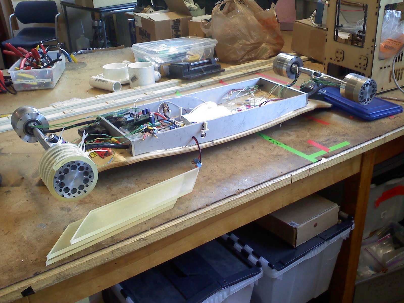
ELB-Heavy will be an electric longboard powered by four custom 500W brushless sensored electric hubmotors and controllers. These new motors will incorporate all of the lessons I've learned so far to make a much lighter, faster, and more robust electric propulsion system.
One of the goals of this board is to make the motors much more covert. I believe this hub motor design does that nicely. It even uses half the stock hub.
The donor board is a brand new Ground Industries (which might unfortunately being going out of business, if rumors prove true) "Patrol" that I got off of ebay for a steal ($140 shipped). I replaced the off-road tires with some MBS street tires. I'm using the board to ride around Cambridge/MIT while I finish ELB. Speaking of this board...I have a set of brand new GI foot bindings and like-new Bionic Trucks (with sets of T4 and T1 cubes) that I'd like to sell if anyone is interested.
Motor Specifications
Power: 500W
Operating current: 18A
Poles: 14
Slots: 12
Phases: 3
Windings/phase: 84
Winding style: AacCBbaACcbB (dLRK)
Stator: 0.75in x 70mm, 0.2mm M19 silicon steel laminations (by Scorpion)
Rotor: Three 0.25in laminations of waterjetted low-carbon steel
Magnets: 28 3/4x1/4x1/8" N40 NdFeB bar magnets
Air-gap: 0.9-ish mm
O.D. : 92.1mm
Width: 54mm
Estimated torque (FEMM): ~3.15 Nm.
Other Specs
Controllers: ??
Battery: 8S LiPo (or possibly 9S LiFePo4)
Estimate top speed: 30mph
Tires: Pneumatic 200x50
So, if you've been following ELB from the beginning, then you may have noticed that these motors produce the same amount of torque (in FEMM) as the ELB's motors (ELB was at 3.1Nm in FEMM and ~2.9Nm in real life). Here is my reasoning for this: ELB ended up with twice the amount of torque I'd ever really need at 10A, and I'm doubling the current for these motors. However, I'm also doubling radius and halving the stator width. Therefore, 2 x 2 x 1/2 x 1/2 = 1 . It's very hand wavey, but I think it should get me reasonable torque numbers. Worse comes to worse, I can always drive them at more current (18A is pretty low as far as PEV's go).
I haven't picked a motor controller yet. Hey shane...want a test bed for your new sensorless controllers? haha
I decided to go with bar magnets this time (instead of custom arc magnets) because of the sky-rocketing price of neodymium. There will be 2 magnets per pole as a first order simulation of an arc (an angle).
I guess one question to ask is, why make a "Heavy" version? The basic answer is that Cambridge streets are awful...and having pneumatic tires is amazing because of that. And Cambridge streets get 3x worse in the winter (which is half the year), so an electric board that can have off-road tires, drive through slush, and you can pick up and take to class is a nice thing to have. Ironically, this one will likely be lighter than the original ELB...
I don't think I'll be able to get started on it this summer, but we'll see.
Anyways, progress report.
All controllers working: check.
All motors working: check.
All essential electronics in box: check.
That means it's time to glue tires! Last time I mentioned a suggestion I got about how to fix my shearing problem when wrapping the tires around the rims. Well...

It works! I tried various ways to clamp the angle, but eventually gave up; the glue is too slick for clamping. However, it was plenty strong for butt-joints, even unclamped. Thus, I hammered in the rest of the motors' steel alignment pins, tightened the screws down, wiped off the motors with rubbing alcohol, and starting gluing on tires.
Steps for gluing on polyurethane sheets/strips to round objects:
1. Acquire a couple packages of 3M Scotch-Weld Urethane Adhesive DB-640.
2. Acquire some plungers from used tubes of epoxy (the cheap double plunger kind). This prevents you from having to buy 3M's overpriced cartridge gun.
3. Acquire a bunch of hose clamps/ low profile zip ties (low profile because they're easier to pull on).
4. Tools: An electric driver or screwdriver, a point-ish glue application device (sharpened stick), rubbing alcohol, paper towels, disposable GLOVES (you'll see why this in caps in a second), something to mix the 2-part glue in.
5. I'm assuming you already have the shape of polyurethane you need cut (bandsaws and hacksaws work well for harder urethanes). Test wrap around part to make sure it'll fit.
6. Wipe off the part with alcohol.
7. Mix up some glue and spread a thin film over the part. Don't use a thick film or it will squeeze out all over the place when you tighten the hose clamps.
8. Spread some glue on the joint ends
9. Carefully wrap the urethane around part and hold with one hand while slipping hose clamps on/over it one by one with the other hand.
10. Grab driver and tighten hose clamps until they're sorta snug (not all the way).
11. Your urethane has probably moved around by now, so reposition it.
12. Continue successively tightening hose clamps until they're all tight.
13. Wipe up excess glue with paper towels/alcohol.
14. Wait 24 hours for it to cure.
This glue is INCREDIBLY messy. Like, 10x worse than the messiest epoxy I've every used, so wear gloves. I didn't wear gloves and got it all over my hands. Alcohol seemed to get some of it off, but not all. It's a really weird feeling: it seems to have increased my hands' coefficient of static friction, without affecting the coefficient of sliding friction, and without being sticky to the touch. Very odd sensation...

 |
| The mess. The other side was even worse. |
 |
| Mostly clean. |
 |
Left to do:
1. Finish gluing on tires (4 hours)
2. Figure out/make new package for hand controller (3 hours)
3. Re-time and program motor controllers (6 hours)
4. Finish mounting motor controllers (45 minutes)
5. Test drive (1 hour)
6. Install fans (5 hours)
7. Install lights (20 hours) (optional)
8. Waterproofing (4 hours + drying time)
Estimated work time left on project: ~44 hours (including lights). I'd call it 90% done at this point. Wohoo!
Now presenting the ELB-Heavy
ELB-Heavy will be an electric longboard powered by four custom 500W brushless sensored electric hubmotors and controllers. These new motors will incorporate all of the lessons I've learned so far to make a much lighter, faster, and more robust electric propulsion system.
 |
| You can see the coils through the polycarbonate if you zoom in. |
One of the goals of this board is to make the motors much more covert. I believe this hub motor design does that nicely. It even uses half the stock hub.
 |
| Things to note: red fiberglass stator protector (like BWD), stock outer-side hubcap, wheel restrained by stock nut, stock axle, stock bolt holes, rotor laminations. |
 |
| Things to note: hole for valve-stem, massive 1" inner-side bearing, through-hub holes for wire routing, odd bolt patterns (actually a 7 hole pattern for steel alignment pins that stop at the seal disk, and the stock hub's 4 bolt pattern). |
 |
| The polycarbonate seal disk has its own thin bearing. The axle really does step like that...it looks like they take 1/2" steel stock and turn it down to 12mm for 36mm of the axle. |
The donor board is a brand new Ground Industries (which might unfortunately being going out of business, if rumors prove true) "Patrol" that I got off of ebay for a steal ($140 shipped). I replaced the off-road tires with some MBS street tires. I'm using the board to ride around Cambridge/MIT while I finish ELB. Speaking of this board...I have a set of brand new GI foot bindings and like-new Bionic Trucks (with sets of T4 and T1 cubes) that I'd like to sell if anyone is interested.
 |
| Sorry for all the fuzzy cell phone shots. I still haven't gotten in the habit of carrying around my camera with me. |
Motor Specifications
Power: 500W
Operating current: 18A
Poles: 14
Slots: 12
Phases: 3
Windings/phase: 84
Winding style: AacCBbaACcbB (dLRK)
Stator: 0.75in x 70mm, 0.2mm M19 silicon steel laminations (by Scorpion)
Rotor: Three 0.25in laminations of waterjetted low-carbon steel
Magnets: 28 3/4x1/4x1/8" N40 NdFeB bar magnets
Air-gap: 0.9-ish mm
O.D. : 92.1mm
Width: 54mm
Estimated torque (FEMM): ~3.15 Nm.
Other Specs
Controllers: ??
Battery: 8S LiPo (or possibly 9S LiFePo4)
Estimate top speed: 30mph
Tires: Pneumatic 200x50
 |
| FEMM simulation. Lots of saturation...oh well. |
So, if you've been following ELB from the beginning, then you may have noticed that these motors produce the same amount of torque (in FEMM) as the ELB's motors (ELB was at 3.1Nm in FEMM and ~2.9Nm in real life). Here is my reasoning for this: ELB ended up with twice the amount of torque I'd ever really need at 10A, and I'm doubling the current for these motors. However, I'm also doubling radius and halving the stator width. Therefore, 2 x 2 x 1/2 x 1/2 = 1 . It's very hand wavey, but I think it should get me reasonable torque numbers. Worse comes to worse, I can always drive them at more current (18A is pretty low as far as PEV's go).
I haven't picked a motor controller yet. Hey shane...want a test bed for your new sensorless controllers? haha
I decided to go with bar magnets this time (instead of custom arc magnets) because of the sky-rocketing price of neodymium. There will be 2 magnets per pole as a first order simulation of an arc (an angle).
I guess one question to ask is, why make a "Heavy" version? The basic answer is that Cambridge streets are awful...and having pneumatic tires is amazing because of that. And Cambridge streets get 3x worse in the winter (which is half the year), so an electric board that can have off-road tires, drive through slush, and you can pick up and take to class is a nice thing to have. Ironically, this one will likely be lighter than the original ELB...
I don't think I'll be able to get started on it this summer, but we'll see.
Monday, July 18, 2011
Fast progress as unusual
The controllers are all working now thanks to Shane. And the problems were, drumroll please... 100% my fault! I guess I shouldn't be surprised. This was my first time hand-soldering (w/o a reflow oven) tiny surface-mount components. And the second board only had 1 issue, so I was obviously getting better at it (I'm still bad at it though...need more practice). Basically just a bunch of poor solder joints, crossed pads, and toasted resistors caused a few components to die - luckily nothing major. The next step is re-timing them (because we messed with the timing so much trying to troubleshoot them). After that, it's programming the handheld controller.
I'm testing the polyurethane glue's ability to make strong butt-joints right now...we'll see how it turns out in a few hours. 5-minute epoxy was too brittle and just snapped at the joint when I tried to bend it. The whole point of this is to see if I can cut the / off of one end of my tire strips and make a /\ on one end and a |\/| on the other (thanks for the tip, josh!). The V joint should get rid of the sliding problem when gluing on the tires. If it doesn't work, I'll have wasted $160 worth of polyurethane sheet, and instead of buying another sheet of it, I'll probably invest in casting materials and cast the right shape tires. Too bad my design doesn't allow me to retrofit mountainboard tires to the wheels.
Speaking of mountainboard wheels, here's a tease frame of what is to come:
 |
| "Hmm...looks like a normal mountainboard wheel." Can you spot the difference? |
Sunday, July 10, 2011
Slow progress as usual
More electrical issues...two of the phases on MC3 (the trouble child) are now screwy. So we're just going to wipe that side of the board clean and start over.
Actual progress:
Tires:
I cut out and shaped all the tires. They're cut out of a sheet of 3/8" 70A polyurethane rubber (which was insanely expensive).
I bought a bunch of hose clamps and massive zip ties to try next. The hose clamps held the gap together well, but another problem came up. The natural position for the urethane is warped when it is curled, which makes the angled-cut edges not want to line up. This means that I can't hold it in place while tightening the hose clamps (which requires two hands). Currently I have no solution to this problem. Maybe a combination of zip ties and hose clamps...I don't know. I can't just glue the edges together, because no fast setting glue is strong enough (it takes a lot of force to hold the edges together). I may end up saying screw it and buying polyurethane casting resin and just casting my own tires.

Shielding sensor wires:
I bought some sweet 5 conductor shielded wire off of ebay. It's kapton coated, which is a nice feature.

Nunchuck:
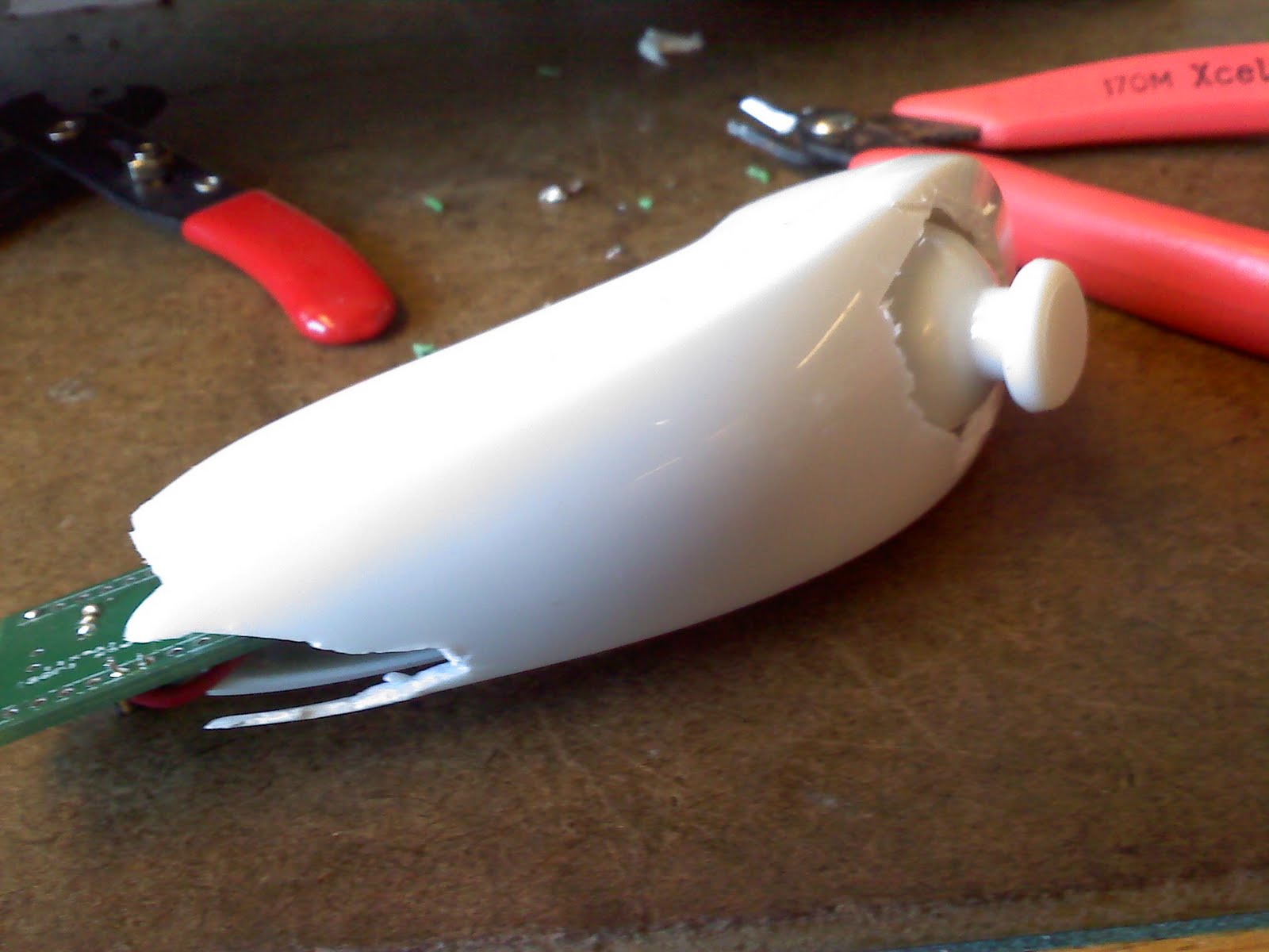
I mostly finished the Wii Nunchuck wireless controller (Shane did the electronics and programming...Thanks Shane!)
Heat sinks:
I soldered a little copper sheet to the 5V regulator (center) on the boards because they get pretty hot.
The MOSFET package on the left (no heatsink) is going to be removed, along with most of the components on MC3.
And that's about it for now. I'm not planning on gluing tires until we resolve these controller issues- they're what's holding up progress at the moment.
Actual progress:
Tires:
I cut out and shaped all the tires. They're cut out of a sheet of 3/8" 70A polyurethane rubber (which was insanely expensive).
 |
| I first started with strips, then cut 45 deg angles on the ends. |
 |
| I tried wrapping a tire around the wheel and holding it with zip-ties. |
 |
| Unfortunately, I need more coverage to hold the gap closed. |
Shielding sensor wires:
I bought some sweet 5 conductor shielded wire off of ebay. It's kapton coated, which is a nice feature.

 |
| Replaced the green mess of wires. |
 |
| I can't open the motors anymore without significant effort, so I just spliced wires. |
 |
| The shield is connected to the sensor ground. |
I mostly finished the Wii Nunchuck wireless controller (Shane did the electronics and programming...Thanks Shane!)
 |
| It's ugly, I know. I need to figure out a different package. I was too optimistic thinking that I could jam it in the nunchuck. |
 |
I soldered a little copper sheet to the 5V regulator (center) on the boards because they get pretty hot.
The MOSFET package on the left (no heatsink) is going to be removed, along with most of the components on MC3.
And that's about it for now. I'm not planning on gluing tires until we resolve these controller issues- they're what's holding up progress at the moment.
Subscribe to:
Posts (Atom)