Search This Blog

Showing posts with label 3D printer. Show all posts

Thursday, January 25, 2024

Random updates

AMD Epyc workstation build

The H11DSi motherboard I had, which was damaged in shipping so I got for free, wouldn't post, probably because it was damaged. The ebay seller I bought two Epyc 7302's from sent me a 7302 and a 7662...the latter is a lot more expensive, but I need two of the same for the dual socket H11DSi. Installed one in socket 1 of the motherboard to test it. The motherboard powered on, but the BMC LED didn't come on like it was supposed to and it never posted.
 

These problems coupled with the price of 7302's and epyc motherboards increasing for some unknown reason, and lack of motivation led to me abandoning this project. Having good computing resources at work helped kill the motivation. I'm currently in the process of selling off all of the parts. For a brief time I owned a Tesla V100 and two P100's, though. These are great for turning watts into double precision FLOPs.
 
Oooo....shiny
 

Home media server

Currently building a home media server/NAS combo in the old headnode's case. I3-13100T, Asrock Z690 Pro RS, 32GB DDR4, 1GB NVMe boot drive, and 6x18TB=108TB raw HDDs. I finally got it built, but it also wouldn't post (UGH). The DRAM error LED was lit, so maybe the new corsair RAM I bought was bad. OR the brand new motherboard memory channels are shot. OR the processor I bought was bad (was supposed to be a new pull...). I bought another motherboard and more RAM to test, one of those things should fix it. The motherboard has 8 SATA connectors, using 6 for the HDDs, one for a Bluray drive (that I'll put old/hacked firmware on for ripping blurays), and one for an external hotswap SATA port, which I'm planning to use for testing HDDs and creating offline backups. 2 HDDs are shucked WD external drives that I got for cheap on black friday. The other 4 are new Dell-branded Seagate Exos I got from serverpartsdeals for a great price with a 3 year warranty. If you need HDDs or server parts, they're a great company to buy from. They shipped the HDDs in anti-static bags, in custom closed-cell-foam holders in a box, wrapped in fancy bubble wrap, inside of another box.

Old case, new guts. Decided to use this one
because of all the space for HDDs.

The software plan is to install Ubuntu and Docker, and run TrueNAS core (ZFS) in a docker container, and the *arrs, jellyfin, pihole/fail2ban, wireguard, etc in other containers, but I haven't fully figured all of that out yet. There are a bunch of online guides for these things. Going to use RaidZ2 for two-drive-fail-safe, which should give me about 65TiB usable space, which is roughly double what I think I'll need in next few years. If I become a data hoarder, there's room for at least 10 more HDDs in there, and the motherboard has a pcie x16 slot for a HBA..also has a couple x4 slots, which might be enough bandwidth. If tech improves a lot by the time I need more space, I'll just replace the whole server. Solid state storage might be cheaper than HDDs by then.

Update: It was the bios. Updating it to the latest let it post. Maybe a 13th gen proc support problem? If that's the case, idk why the DRAM error light was on. I'm keeping the 4x8GB RAM installed. The 2x16GB RAM will be useful if I ever decide I need 64GB. I returned the spare motherboard. I installed ubuntu on the 1TB NVME drive, uninstalled a bunch of crap that comes with it, and ran short SMART scans on the 6 HDDs. I need to figure out how to use badblocks, smartctl, and smartd to check and monitor HDD health.

3D Printers

I bought a creality K1 on black friday. It's awesome. 


It was only $380. I have about double that "invested" in the wanhao i3 and the K1 prints way faster and better. Amazing how far FDM tech has come. Unfortunately, this is going to hurt motivation to finish CubeXY. I'm planning to transition to prusa slicer from cura soon.

Other

I put a trailer hitch + wiring kit on my prius.

Curt brand. They sell them for just about every vehicle, and the instructions were surprisingly good/easy to follow. Only thing missing was how to deal with the plastic underbody cover. I took it off first, but apparently didn't have to. Getting it back on after installing the hitch required cutting it in a couple places. Of course, that means that if I hadn't taken it off first, then whoever worked on that part of the car next would have to cut the cover off (or take the hitch off), so maybe it was a good thing to do. Overall, took about 2.5 hours. Anyways, the reason I did this is that basically every experience I've had with renting a UHaul truck/van has sucked. Now I can just rent a utility trailer, which is a lot cheaper, too. Should pay for itself in 3 trips where I don't have to rent a truck/van. 

I made a reservation for an Aptera a little over a year ago. They recently removed the estimated delivery date, though, sigh...I think the prius will last a few more years at least, so maybe I'll get the solar car by then. 

I was at AIAA SciTech for a day to give a talk. Unfortunately caught COVID for the first time, ugh. Over it now. 

Haven't done much in the garage. Cleaned a corner of it, so progress? Ha, one day...

1/30/24 update:  

I got to use my hitch! I bought a Craftsman 152 table saw off marketplace. It was in fantastic condition and for a decent price. It was on a sled with wheels, which was convenient. I towed it home on a 5x3' home depot ramp trailer that only cost $25 to rent. I backed the trailer up to the garage and rolled it right in.

Bad pic, mosquitos were swarming me

I'm going to sell the 113 saws, probably as they are (in parts). I decided I'm far more likely to actually make things if I don't have to spend 10+ hours rebuilding one.


Sunday, November 19, 2023

Well that sucked...

Can't believe it's been over a year since I posted anything...nevermind, I can, cause most of 2022 and 2023 sucked. Amid a plethora of life crises, I found out in September that my comps were expiring in December, which meant it was do or die for my PhD. That and all the other terrible things that happened made these the worst few years of my life. But this isn't a life blog; I'll spare you the depressing details, so fun things only:


PhD

First, and finally, after over 7 years as a PhD student and over 10 as a grad student, I'm a Dr. Since I work with launch vehicles, do related research, and am a thermal-fluid subject matter expert, I guess I'm now officially a rocket scientist? I'm so glad it's over, feels surreal, or maybe that's just shellshock+severe burnout+trippy-exhaustion. I'm not sure I'd ever recommend getting a PhD for an aerospace engineer, except maybe if you want to do controls or teach, but I definitely don't recommend trying to get one while working full time. Once you start making real money, motivation and time plummets...there's nothing quite like being on grad-slave wages to motivate finishing. I've heard working while studying is not too bad with a flexible/supportive work place, an excellent advisor/department, and a straightforward project. NASA is a fantastic place to work and, compared to most companies, very understanding of life problems and supportive of higher education. My research had data quality issues (from one experiment I didn't design or run) and was anything but straightforward. That + life :( + real job $= zapped motivation to work on it = 7 year PhD. Don't do what I did, just don't. I'm glad it's over.

The projects that were part of the PhD were pretty cool, though, both related to microgravity propellant slosh dynamics. I got to ride in a Zero-G plane, which was the coolest thing I've ever done and funnest experience I've ever had.

Floating upside down

About 1/3 of the plane puked, but I don't get motion sickness, so it was a blast for me. If you ever get the chance to go on a zero-g plane, do it. I'm still writing a bunch of papers from this research and stuff that spun off it.


Mill

I got a mini mill off marketplace for a steal.
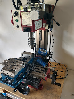
Mini mill is mini

Now I have a mini-mill and mini lathe (relocated), though haven't done (had the time and energy to do) much with either yet. It's sitting on the antique workbench I refurbished....oh! I learned from a car guy why the oil-based paint took forever to harden: FL humidity. You really need to use a dehumidified paint booth in FL. I'll probably make one out of a pop up tent and AC/dehumidifier next time I need to paint something.


Really, it's not a life blog...well, maybe a little

I'm jealous of people who have big home machine shops. That's been my dream since MIT, actually probably since high school, although I can't remember much of anything from back then. I know the me-from-then would be depressed to hear I'm still not quite there yet. I can now see the light at the end of the tunnel, but getting there is, and will continue to be, so much slower than I'd like. Part of the reason is this house...the garage has a low ceiling and is at the bottom of a steep driveway, there's just no good way to get a large mill or lathe in it. Also doesn't have land to build a shop. So I'm planning to move...eventually. House has a bunch of issues that have to be fixed before I can sell it, but it's not like I can afford a house with the current interest rates even after selling this one, so heck knows when that'll happen.

Also, I mentioned NASA is a great place to work, but the salaries are badly lagging industry ...That was always to true to an extent, but inflation and talent demand from all of the rocket companies has made it so much worse the past few years. I applied to blue origin and got an offer way (wayyy) over what I make now, but it came down to a quality of life (more hours, no work from home, less PTO, etc) vs. money thing. I ultimately stayed at NASA. I mentioned my life was sucking...not going to try to convey that here, but most of that wasn't money driven, so I think choosing QoL over money was the right choice, despite a lack of funds being one of the reasons I don't have a nice shop.

I know I said this wasn't a life blog, but I want to say this: life is messy. There are so many posts, articles, blogs, vlogs, etc showing people having everything you might want and living perfect lives...all of it is garbage. They only show you what they want you to see. Unless you're rich, real life isn't like that, so don't feel bad when you see that crap. AI is just making that worse because now pretty much everything on the internet can be faked: pictures, videos, and even whole blogs. There is so much click-bait like "I built this [insert amazing thing] in 1 day!"...bullshit. Them lying like that to generate ad revenue bugs the shit out of me if I let it. I try to be open/honest about how much time and effort the projects I document in this blog take, and I mention everything that inevitably goes wrong. I also don't, and will never, monetize this blog. Ignore all the BS, do your own thing, go at your own pace, and try to have fun when life isn't sucking. I know I'll probably be 40 before I get the shop I want, about 20 years later than I wanted, but I'll get there.


Small Parts Organization

While I didn't have time to do much else related to the shop, I did have time to finally organize all of my screws and small parts. You can actually see some of the organizers I started to accumulate back in late 2021 in a picture in this post, but I didn't start organizing in earnest until this year. The organizers are the Hypertough ones from Walmart, which are the same as the HDX ones from Home Depot except the HDX ones have orange latches and inserts instead of red. They come in 2 packs, used to be $10, then it was $12. Ended up needing over 30 of them. I designed bin inserts for the organizers, which actually cost more in filament than just buying more organizers, though they do save space and are convenient. I designed stackable cabinets to hold them.
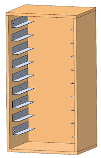
Small parts organizer cabinet

There are a bunch of neat cabinet designs out there for these and other brand organizers. The organizers I'm using had the lowest $/volume ratio I could find, and I think this cabinet will take less time to build than one based on dados. The panels are 3/4 plywood, glued and pocket-hole-screwed. The rails are 1.5x1.5x1/16" aluminum angle, which I can source locally from a place in orlando for cheap, and they may even cut them for me, though I could cut them with my miter saw or chop saw if I really had to. No need for wheels, part of the point of the organizers is that I can pull out the one I need and take it to wherever I'm working. I haven't built the cabinets yet because time and money, and a (functional) tablesaw would be nicer than a circular saw for cutting the panels. The organizers are just stacked at the moment. I also organized medium-sized parts, like arduinos, in storage bins:

Organized

Oh, and as shown above, I moved the printers out of the garage into a spare bedroom-turned-hobby-room.


Rocket Garden

I 3D printed a rocket garden for my desk at work. 
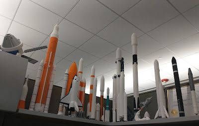
 
Rockets!

All documents are digital now, so I decided to fill up the drab cubical real estate with these. Kind of an old pic, there are more now, and along with a 1/30th scale Apollo lander with astronauts and a rover off to the right. I'm working on a mercury-redstone and the JWST now. I found all of these files for free on the internet, though I occasionally fix things I don't like about them.

Wanhao i3

My ancient shitty, yet super upgraded, wanhao i3 just passed the 25km of filament printed mark! It works juuusssssttttttt well enough to kill my motivation to finish CubeXY. That's also why I haven't bought a new printer, cause that'll just kill my motivation more. Instead, I spend more money on the i3 because that makes sense (/s). I replaced the glass bed+PEI sheet with a magnetic build plate, which is night-and-day easier to use and was worth every penny.
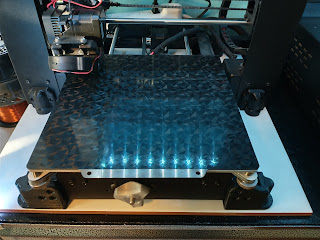
New build plate
 
You can see the knob from a new Y-axis belt tensioner in the above pic, too. The old printed support structure crumbled, so I switch it to back-braced. The braces are now out of the way, though they are not quite as stiff.
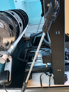
 
New braces
I printed a bunch of random things over the past year, like this mechanical dragonfly:

For the wings, I printed one layer of clear PETG on a textured build plate, then used atomic filament bronze PETG for the rest. I think they came out decently realistic. I think the oof stones might be my favorite:

Printed with Atomic Filament Marble PETG

Future plans:

Table saw: Come December, it'll be the 2 year anniversary of having a disassembled 113 table saw in my garage. I bought a second one recently for spare parts and it has a much nicer fence than the original. I should be able to make one nice saw from all that, and sell the left overs. I will finish it. All the pics and the blog entries on this have turned out to be super helpful since I don't remember what goes where.

Workbench: 3-year anniversary, and I don't have all of the tools that were going to go in this anymore, so it needs some re-design... 😅 I'll definitely finish this. Need a working table saw first. 

CubeXY 3D printer: over 4 years (RIP). I still have all of the parts, just never got around to assembling it. But I will finish it, and it might will be awesome. 

H1 rocket engine turbine display case: Now that I finally have a mill, I can cut the parts for a stand for this. Need to de-rust it first.

Homelab: I have access to compute clusters at work, so I don't have plans to build a new homelab cluster. I have (very) slowly been accumulating parts to build a dual AMD EPYC machine, which, if my calculations were correct all those years ago, it should be nearly as fast as my entire cluster was. I still have the old head node, not exactly sure what I'm going to do with it yet, maybe turn it in to a NAS since it has a bunch of drive bays. I want to set up some self-hosted services. 


That's all for now.

Thursday, December 30, 2021

Workbench, part 3

Workbench progress.

Pocket hole screwing + gluing the table saw box on.

Those are Wen 4" pocket hole clamps. They just barely fit 2x4 pocket holes edge on like that. They help keep the 2x4s aligned while driving in the pocket hole screws. 

Adding edge banding to the shelves. Tiny $12 palm-sized iron works perfectly.

Needed some edge band trimmers, so printing those while I put the edge banding on

The edge band trimmers use M3 melt in inserts

Also did some of the M3 melt in inserts for CubeXY. Yes, that's still going to be a thing...eventually. Got to use one of the melt in insert soldering iron tips I turned awhile back. 

These work great. Found them on thingiverse.

Edge banding done, time to stain:


Factory edge=bad

I sanded them with 220 grit, wiped the dust off, cleaned them with mineral spirits, and then sealed them with stain primer. I stained the edges (banding) of the table saw shelf golden oak, but didn't bother staining the rest of it since it won't be visible. I stained the router shelf "golden pecan", however, it came out a lot redder than I was expecting. Lessons learned: The Varathane "premium" stain colors are NOT the same as the "classic" stain colors. The classic golden pecan doesn't have much red in it and is what I used for the base shelves. The premium golden pecan is actually very close to the classic "Ipswich Pine". Meh, luckily it's a workbench, and I'm already mixing a ton of wood tones, so it doesn't really matter. The edge banding didn't take the stain as much as the plywood. Also, factory edges, while straight, need to be cleaned up because the stain will accent the underlying grain.

While I had the printer going, I decided to use up some old shitty (Eryone brand, bleh) filament I had and print some wood working tools. 


♫ Part of a marking gauge, two mini sanding blocks,
and a set of center finding of guides ♫ (3rd day of Xmas)


Right angle clamp blocks, printed two sets ~800g

Time to install the table saw shelf:

Screwed on the table saw vacuum adapter

Clamped, then screwed down the shelf.

Looks good, very rigid

I won't be able to see the top surface, so I didn't bother filling in the screw holes. I installed the router shelf next: 


Left side of shelf. Center: The Mini-Motivator 

This was tricky. I drilled (normal sized, not the "HD" ones) pocket holes in the bottom of the left side of the shelf to screw to the left vertical 2x4s. There's a 3/16" thick spacer that has to go on the right side between the shelf and the horizontal 2x4, which I made by gluing together strips of 1/8" and 1/16" plywood. That shim is necessary because the left bandsaw pivot bearings mount to the top of that horizontal 2x4, and they need to be at a specific height. I used glue in all of the joints and used a ton of clamps to hold everything in place while I drove in the pocket hole screws. Leveling the shelf required a lot of unclamp-shift something-clamp-check level operations. Weirdly, while I was doing that, I realized that the shelf couldn't be clamped flush to the horizontal 2x4 in order to be level. 

Uh-oh...the shim needed shims.

The shelf ended up needing to be spaced about 1/16" lower at the back than the front. It was then that I checked level of the top of the horizontal 2x4: it was slanted. Hmm... re-measuring the back vertical 2x4 it was resting on showed that it was about 1/32" too long. Then I checked the CAD. Ugh, that same 2x4 was 1/32" too long. Didn't notice because it was such a small interference. 1/32+1/32 ... there's my extra 1/16". By this time, it was too late to fix because I'd already screwed it all together and the glue had partially set. So I used the handheld belt sander to sand down the top of the horizontal 2x4. 


Now it reads level. 

I also screwed on a few more horizontal 2x4s. These required a bit of fancy clamping, but all the joints came out good. 


A bunch of the horizontal 2x4s need notches cut in them. Some need to be re-sawn, which I'll need the table saw for, so I'm going to start refurbing that soon. 

Friday, May 8, 2020

CubeXY X-axis Re-redesign

One of the great things about hobbies is the lack of deadlines. Unlike in the real engineering-world, I can keep tweaking and perfecting designs as much as I want. This printer is turning out to be a great outlet for that.

I mentioned in an earlier post that the "12"mm SS rods that come with the CubeX are undersized. I finally measured them with a micrometer. They're 80um under, which for linear bearings, is WAY undersized. The THK linear bearing spec for 12mm LM shafts calls for -6 to -17 um. That probably contributed to the bad bearing wear I saw on the stock bearings. I purchased 4 new 12mm rods from PDTech on eBay: they actually listed a diameter tolerance spec, and they were case hardened, both of which are important for linear shafts (and neither are common for cheap chinese linear shafts). The only downside is that they're chrome plated steel, not stainless steel, but case hardened stainless steel shafts are very expensive, so I didn't buy those. I only purchased four since only four of them will have linear bearings on them. They ended up being about 11um undersized, which is right in the middle of the THK tolerance range. They result in noticeably smoother linear bearing movement and less (almost no) slop.

I purchased them long, partially because some of PDTech's non-standard lengths were actually cheaper than their standard lengths (455mm was cheaper than 450mm, not sure why), but mainly because I plan on making the printer taller. I mentioned this in passing in a previous post, but there is a lot of room between the top of the top aluminum cylinder shaft holders and the top of the acrylic shell. I can safely increase the length of the vertical shaft/rods by 40mm and still leave plenty of clearance between the hot end assembly and the lid. 40mm is convenient because the stock vertical shafts are 400mm long, and the stock X-axis shafts are 440mm long, so I can replace the 4x 400mm stock shafts with the two 440mm long old x-axis shafts (rear of printer) and two of the new tighter tolerance shafts (front of printer). I'll have to redrill 4 screw holes in the acrylic shell, and cut some acrylic out around the XY motors in the wire-mounting back plate, but that's pretty much it. Totally worth getting another 40mm of Z travel, for a total of about 325mm.

Taller CubeXY
While trying to find actual tension force measurements of belts in corexy printers (never found any), I stumbled across this interesting post on belt compliance. This person measured belt compliance at 10N preload (tension) + 10N. Basic 6mm GT2 fiberglass reinforced belt (like the kind I bought), has  modulus of 0.0067 %/N, while 6mm GT2 steel core belt has a modulus of 0.0024%/N. The given example is a 1kg carriage being accelerated at 3000 mm/s2 with a 1000mm belt. 1kg*3m/s2=3N. 0.0067%/N*3N = 0.02%. 0.0002*1000mm = 0.2mm, which is about half a nozzle width, which would probably result in very bad ringing. I had been planning to drive my corexy, which has approximately 2m long belts, at 6000+ mm/s2, with an approximately 1kg carriage. Doing this math for my printer yields 0.8mm of stretch, which is terrible. A steel core belt would be about 0.29mm of stretch. I bought some to try. The disadvantage of steel core belts is that they're heavier and stiffer, which means less power ends up in the motion of the carriage. Steel core belt minimum radius is also larger, mainly to prevent kinking and fatigue, so I may not be able to use them...we'll see. I'll probably start with fiberglass core belts. This post has a lot of details on belts.

X-axis Re-redesign

Due to the FEA results from the last post, I decided to completely redesign the X-axis to make it stiffer. 


The X-axis plate is flat now, and the pulley blocks also hold the linear bearings. The Hemera exttruder has been rotated 90 deg. The x-axis plate is 149g and made of aluminum. It's about 25% lighter than the previous steel design, and 45-75% stiffer, depending on the bending mode. It'll be machined out of scrap 1/4" ground plate. The pulley blocks will be machined from T6-6061 bar stock. The fan mount plate will be band sawed out of 1/8" aluminum plate, and I'm going to use flush press-in threaded inserts in it instead of threading it. The motor-carriage mount will be milled from 2x2" x 1/8" wall square aluminum tube, which holds the extruder motor on the inside almost perfectly. Unfortunately, almost all of the previous machining I did won't be used. Luckily, the nozzle ended up in very close to the same place, so the same bed plate can be used. I will have to print new bed mounts, though, because the bed has to be shifted in +Y 5mm. This system should result in  much stiffer X and Y axes. Here's a close up of the new extruder assembly:


This version is far less elegant than the previous one. The belt tensioner on the previous version was very simple and compact. This one uses the two stock X-axis belt tensioner cylinder things mounted inside of a 3D printed ratcheting assembly. I'll use a wrench on the printed hexes to tighten the belts, then tighten the button head screws down to hold the tensioner in position. Mounted off of that assembly is the inductive probe, which is conveniently closer to the nozzle now. The other side of the extruder has the fixed belt mount which takes each belt in and turns them 180 deg for plenty of belt engagement. Both the belt mount and radial fan are screwed to the 1/8" aluminum plate, which in turn is screwed to the side of the Hemera extruder motor. The fan location and duct are also less elegant. The previous duct completely encircled the nozzle. This one only has room to blow from one side. Because the belt heights are fixed by where the motors are mounted, and the requirement that belt segments be straight, the belt tensioner and fixed belt mount could only be located in the locations shown. Also, since Hemera was rotated so the length was along Y, the only place with room for the fan was on one of the X faces. Because the fan has its inlet on one side, that restricted the fan to the -X side. The fan also couldn't be located too far in +Y or it would impede the cooling flow from the hot end cooling fan. All of these things meant that the fan had to be mounted kind of high and in the location as shown. The LED light will be taped under the motor. I tried about every way I could think of to come up with a better way to configure the extruder assembly, but this was the best. While it's not as pretty or elegant, this should be a far stiffer and better performing design.

I've put in new material and screw orders. I should be able to finish machining the new X-axis plate next week. I'll start 3D printing the new plastic parts this weekend.

Tuesday, April 21, 2020

CubeXY Fabrication Part 3 and X-axis redesign part 2

I re-machined the pulley blocks today. They required a relief cut in them for the longer 450mm rail. Speaking of which, here's the "new" (ugh, see below) X-axis design.

Right pulley block

The x-axis plate is contoured for mass savings, which I extended to the 3D printed pulley blocks for aesthetics. The M3 screws were also shifted around some.

I also pressed-in the linear bearings to the old aluminum x-axis plate and test assembled it on the printer.


The good news it that is slides well, and I think I got the linear bearing spacing correct. The bad news is that this let me see a bending mode I hadn't thought of until now. Previously, I analyzed what I thought was worst case: both motors being used to apply max force such that the x-axis was maximally accelerated in y. I applied this y acceleration to the FEA model with both ends of the x-axis restrained. This is not the worst case, though. For corexy, in order to move diagonally, one motor applies force while the other does not. This causes both the X and Y axes to translate, resulting in diagonal motion. Here's the basic corexy belt layout I discussed a few posts ago:


If you spin the bottom right motor clockwise, for example, that will pull the x axis carriage in -X and the whole x-axis in +Y, resulting in diagonal movement. All of the belts are still tensioned, but belts H and D are tensioned more, by exactly the force required to accelerate the axes' masses, and that force is applied by the motor torque to the pulley. Because H (and D,  M and J, but they don't matter for this discussion) has more tension, there is a net torque on the X axis assembly about Z, which has to be countered by the Y axis linear bearings. Remember how I said linear bearings don't handle torque loads well? Oops. But there's another problem. If the X-axis is not very stiff, then the net force in segment H will cause the X-axis to be bent. My design is essentially a beam supported by two rollers, or if you think of the system as static, a pin (pulley P1) and a roller (the linear bearing under P2). This is causes a different mode shape, one that results in more deflection than the previously analyzed case, despite using the force of only one motor instead of two.

I removed the Y axis acceleration (left gravity), left the radial roller supports in the linear bearing holes, left the fixed support in one of the shoulder bolt (pulley) holes, and applied half the previous force (one motor only) to the other shoulder bolt hole. This caused negligible Z deflection, but the Y deflection of one side relative to the other was about 1.8mm! Yikes.


This is the bending mode I was seeing with just the linear bearings and aluminum x-axis plate (no steel rail)...I was able to move them about 5-10mm relative to each other. If there's any play at all in the bearings or frame (impossible to remove all of it), and if the beam connecting them isn't perfectly rigid (never is), then the linear bearings can move axially relative to each other. In the FEA case above, no displacement in X of the linear bearing surface was allowed (bearing or frame slop), so it's likely that the real world deflection would be > 1.8mm.

The frame will be stiffer when the 12mm rods/shafts are locked in place (set screws) and the acrylic shell is on, but that won't eliminate bending in the rods and aluminum brackets holding them. There's also no way to the play between the undersized rods (talked about previously) and the linear bearings...I can add some pretension, but I don't think it'll be enough. Accelerating much slower (~factor of 10, ugh) also fixes this problem, but slow printing was something about this printer I was trying to fix. Ultimately, the right way to handle this problem is to make the X-axis stiff enough to not deflect significantly, which I'm not sure how to do at this point.

The weird thing is that other corexy's aren't immune to this, including ones with rail guides. Linear rails are designed to handle torque, but they still don't limit axial motion, which is where this bending mode comes from. This X-axis design is actually stiffer than Railcore II's unsupported MGN12 rail, at least according to my FEA, so how does that printer work so well? This lead me to re-examine my model inputs, specifically what I'm using for force and acceleration.

I first used just the motor torque and pulley radius to calculate a force. I then used an online calculator for stepper motors that accounts for rotor inertia, applies a factor for reducing the holding torque to a more realistic torque value in order to reduce positioning error, and applies another factor for microstepping torque reduction. I could have written my own simulation program, and have for (much larger) linear motion applications before, but meh...if a calculator exists, why not use it. This dropped the max per motor acceleration to 3 m/s2 from a previous 32 m/s2. I also checked forums for maximum real world accelerations for other high performance corexy printers. It seems that 6-20 m/s2 are about the maximum. 20 m/s2 results in 200mm/s in 1mm and 0.01s. I'll probably redo these analyses with that.

Update: I re-ran the final design with 20m/s2 and 6m/s2. 2*20m/s2 in case 1 (the bending mode shown previously) resulted in a Y deflection of 0.062mm, and 0.55mm at the nozzle and 1mm at the unconstrained y bearing block for case 2 (the bending mode shown above). 2*6m/s2 in case 1 resulted in a Y deflection of 0.017mm, and 0.16mm at the nozzle and 0.3mm at the unconstrained y bearing block for case 2. The Y deflection for 20m/s2 is still unacceptable, and I'll probably have bad ringing at 6000mm/s2 if the motion is somewhat diagonal. Not good.

Sunday, April 19, 2020

CubeXY Fabrication part 2, and X axis plate redesign

Made some more progress fabricating.

I made 4 brass soldering iron tips for melt-in inserts. The brass rod cost $6 (only used half of it), and it took about an hour to turn these.


I designed them for combination US and metric. They cover M2-M5 and 4-40 - 10-32.

I milled the bed plate (with a lot of help, thanks Anthony). While programming prototrak is like riding a bicycle for me, mastercam apparently isn't.

bed being milled
Top
Bottom
The 1/4" cast aluminum plate stock, purchased from midwest steel supply, arrived with a few pits in it. I guess despite being ground, basic material handling of these large sheets results in pits. One of the mill clamps also left a noticeable dent in an edge. Otherwise, it came out well. I'll probably end up lightly sanding the whole top anyways to improve bonding. 

Next was test milling linear bearing holes to find a good press-fit diameter. 

I had to turn a small part to push this out after I pressed it in.
Then actually milling the x-axis plate (again, thanks Anthony). 


This felt a little flimsy. Uh oh... I went back and checked math/FEA. First thing I noticed was that the big chamfers on each side interfere with the X-axis carriage at both travel limits. Oops. I calculated what the max possible acceleration of the Y-axis could be given it's estimated mass (~1kg), the motor torques and inertia, etc. Came out to about 64 m/s2, which is likely an over estimate because it doesn't account for friction or microstepping losses. I used that and 1g applied to a mock extruder assembly, the X-axis rail, and X-axis plate in an FEA model. I added radial restraints to the inside of the linear bearing holes and fixed constraints in the shoulder screw holes. The parts were "bonded"...bolt contacts are a pain to add in solidworks simulation, and they really slow it down. Considering the close screw spacing, I expect maybe 5% more deflection in reality than predicted by the bonded contacts. The results showed a max deflection at the nozzle location of about 0.19mm in Y and 0.07mm in Z. Some of the Z deflection came from 1g, which will be accounted for because that's constant. The rest came from torquing of the X-axis plate. That amount of Z is concerning, though...it'd probably cause poor bonding in one direction and extruder skipping in the other direction. The Y deflection is also concerning...that'd definitely be noticeable, and probably manifest as bad ringing or bulging layers. I tested both forward and reverse acceleration to see which was worse. I also did a mesh independence test. I then started modifying the design and running FEA. Took about 30 iterations, but finally settled on something better. 

I targeted half of both of the baseline deflections as my goal. I figured out I didn't have room in the Y-axis to make the plate thicker, which would have been the best way to improve bending stiffness due to Y-axis acceleration. So the plate can't be thicker than 1/4". Tests making the thin beam portion slightly wider helped Z deflection some, but didn't significantly help Y. I also tried making it thicker just around the linear bearings, where I did have some room to make it thicker, but that didn't help very much. The stress contours showed that almost all of the material around the linear bearings, except the portion near the thin rail mount beam, was essentially unloaded. Since I couldn't make the rail mount beam thicker, I had to change materials. Steel and stainless steels have a modulus of elasticity about 3x higher than aluminum. Unfortunately, they're also about 3x denser. I decided on SS304 because I can buy it for not much more than carbon steel, and it won't rust. One small advantage of using SS304 is that it's CTE will match that of the rail (some steel alloy) better than aluminum. I realized that extending the rail from 430mm long to 450mm would stiffen the transitions to the rail mount beam by effectively making that region thicker. Final results: Y deflection of 0.11mm and Z deflection of 0.038mm, 2x the mass of the X plate (about 10% more moving Y mass). Not terrible, I got most of the way to the 1/2 deflection goal. 

(Preliminary) Design of new X-axis plate

Final FEA run,100x exaggeration, showing contours of Y-axis deflection 
Contoured ends and pockets under the rail resulted in about 30% mass savings over solid. I also redesigned the X-axis belt tensioner part to accept the chamfers. The pulley blocks will need a chunk milled out for the longer rail and a M3 hole relocated, and the linear bearing blocks will need to be re-designed and re-printed. 

I'll probably go ahead and press the linear bearings into the old x-axis plate and use it to test the Y-axis shaft spacing and motion. 

To do:
1. Finalize re-design
2. Buy a longer MGN9 rail. oof
3. Buy a piece of SS304 bar stock
4. Re-machine pulley blocks
5. Re-print linear bearing blocks
6. Mill new X-axis plate
7. Get back on track.