First, a brief review of standard fan control methods. There is a lot of confusing terminology out there regarding small dc fan control. 2 pin fans just have power and ground. These can be controlled either by varying voltage linearly, or by PWM'ing the power line. The former only works down to ~half the rated voltage for most fans or they don't have enough power to start. The latter requires a PWM fan controller. 3 pin fans have an extra wire that outputs the tachometer readings. This is useful for measuring fan speed if the power source is constant, i.e. not PWM'd. If the power is PWM'd, then the sensor is, too, which usually messes up its readings, unless the PWM frequency is much greater than the RPM. 4 pin fans have power, gnd, tach, and control wires. In addition to the two methods mentioned for two pin fans, these have a third option for control. In stead of PWM'ing the power wire, a low voltage/low current PWM signal can be sent to the control wire. The fan's internal electronics then handle the actual power PWM'ing. This has the added benefit of not screwing up the tach sensor readings because the voltage on the power wire is still consistent. Unfortunately, finding a cheap controller for these fans is difficult. Noctura makes a ~$20 manual pot one, but that's the only one I could find. I'm reviewing the three most common cheap chinese eBay ones here.
Fan Controller 1

This is the controller I reviewed in March. It can handle two fans of 2, 3 or 4 pins in 2-pin control mode. 12-24V input, max 4A output. It will automatically adjust the two fan outputs' duty cycle based on the reading from a temperature probe.
The control chip is a TC648 dedicated fan temperature controller. Unfortunately, the PWM switching frequency is about 30 Hz, and is audible/visible and annoying. If the switch is up, the potentiometer allows for tuning the turn-on temperature, which is nominally 30C, and always about 20C lower than the max temperature, nominally 50C. The pot is very sensitive. If the switch is down, supposedly the temperature set points are fixed at 30C and 50C, but I don't think they're accurate. At 12V, the acceleration is smooth, but very slow. At 24V, the acceleration in the control band is underdamped, so the fan speed oscillates wildly. Note that the 2A or 3A versions have one missing FET (like the one pictured), but the 4A one has all of them. Because this one pulses the power pin, there is a voltage drop across the board that results in the fan not operating at the same maximum RPM as if it was plugged directly into the power supply.
Conclusion: Not recommended.
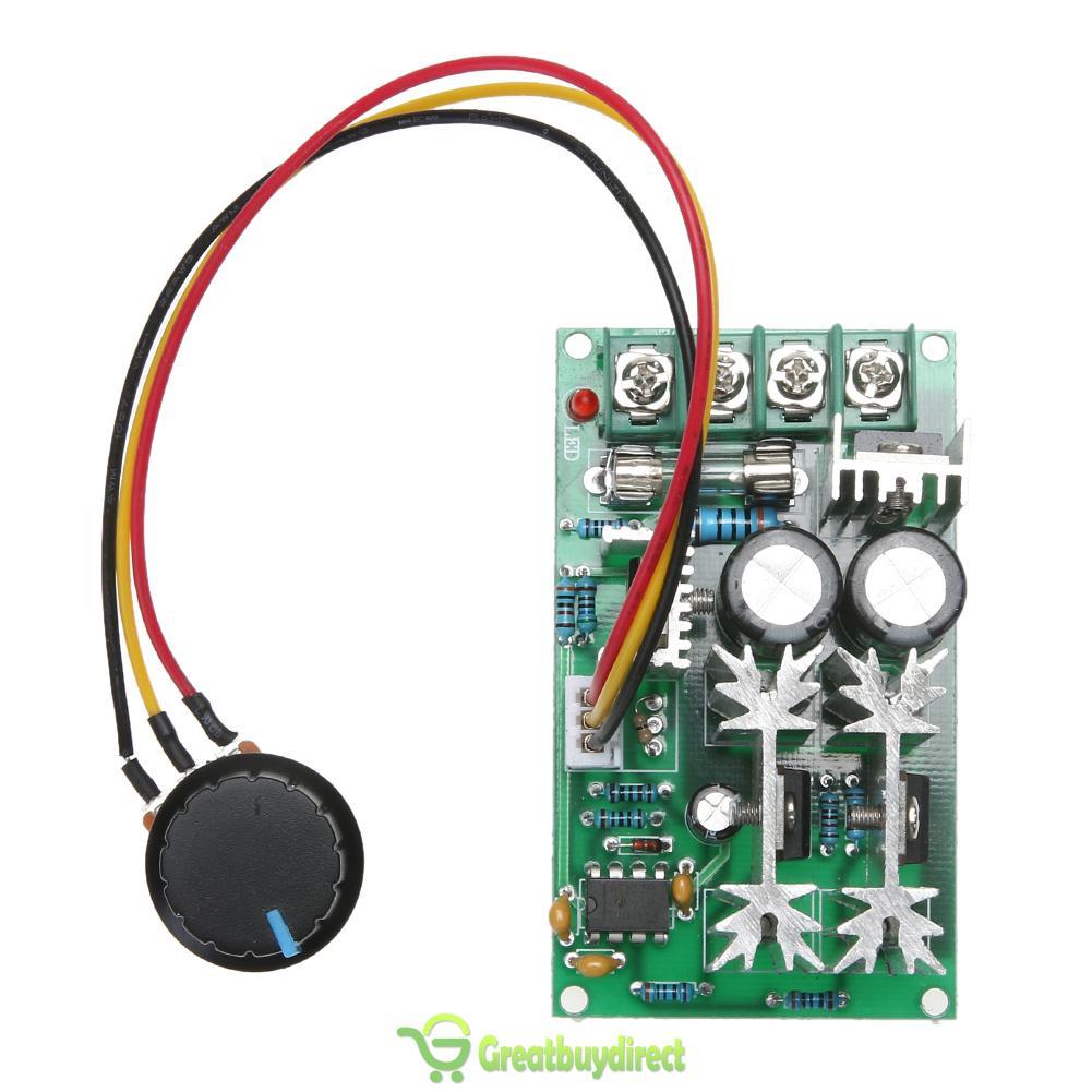
Fan Controller 2

The temperature control works fairly well: acceleration is smooth in the control band. The pot controlled fans are adjustable from about 10-100% duty cycle. It reaches the same max RPM as if the fan was directly connected to a 12V source. Board current consumption is very low, a few 10's of mA.
Conclusion: If you have 12V 4-pin fan(s), and one of those temperature ranges works for you, and especially if you need to manually set two other fans as well, then this is a good pwm fan temperature controller for you.
Fan Controller 3

It works great. Acceleration is silky smooth from the low temperature set point to the high temperature set point. It reaches the same max RPM as if the fan was directly connected to the power source. Acceleration is a little slow, likely because of the potted temperature probes taking a long time to heat up. It's faster than Fan Controller 1, though. I haven't tried this with voltages other than 12V input, but my guess is the behavior would be the same due to the buck converter.
Conclusion: This board is awesome. If you need to do temperature control, especially dual zone, of 4-pin fans of 12-60V, then this is the board for you. I will be using this in my homelab's cabinet to control the heat extraction fans. The only feature I wish it had was automatic stop/start of the fans so they wouldn't run when below the min temperature threshold.
Fan Controller 4
Hopefully this review will help someone in the future choose a PWM fan temperature controller.
As I mentioned above, I will be using Fan Controller 3 moving forward. I had to create a new wiring harness.

I'm using FAN1's output to control all three fans. Because their total current is greater than 3A (limit of a fan connector), I had to run bypass pwr and gnd wires directly to the power supply. I pulled the pwr pin from the 4-pin fan connector that plugs into the controller to prevent current from being run through the connector. I also soldered small power wires for the controller to the fork terminals on the bypass wires. The three PWM control pins are wired together in the harness to the single blue wire connected to the controller, but only one of the yellow tachometer wires is so the tach signals don't mix. I 3D printed some terminal covers for the power supply because it didn't come with any. I'm going to 3D print a green tray to hold the controller PCB and to shield its back from shorting. I'll set the set points to 30C-40C, and the temperature probe will be taped to the top back of the cabinet. If that part of the cabinet gets to about 30C, then the heat extraction fans aren't moving enough air to prevent hot air from recirculating to the front of the servers, so they need to ramp up.
When I was testing Fan Controller 3, I noticed that the 10% duty cycle command only corresponded to 50% of the max fan RPM and the 100% duty cycle corresponded to max fan RPM. At first, I thought something might be wrong with the controller, but measuring the average DC voltage of the PWM control pin showed that it, at 10% duty cycle setting, was reaching about 12% of the voltage at max duty cycle duty cycle setting, so that meant the controller was probably fine. Unfortunately, Mechatronics, the manufacturer of the fans I purchased, does not publish PWM vs. RPM data. I found digging through their website that 50% is the minimum fan RPM, which is what I observed earlier. It's unfortunate that those fans don't allow for lower RPM operation. I measured operating current and found that at the lowest setting, the fan draws 19% of the power it does at max RPM, which is a savings of ~35W for all three fans. It'd be nice if the fan controller could turn the fans off, but that'd only save an additional ~8W. Compared to leaving them running at full speed all of the time, I'm probably saving somewhere around $30/year (assuming the fans are at min throttle half of the year) by implementing fan temperature control.
On a separate note, I tried installing a second fan on the CPU cooler on CPU1 in the headnode. The Cooler Master Hyper 212 Evo's come with an extra pair of brackets for mounting a second 120mm fan on the other side of the heatsink. The 120mm fans and y splitters I bought were 3 pin, though, instead of 4-pin, which means that both fans ran at 100%. It'd have been better to buy another 4-pin fan and a 4-pin splitter cable so that they could be throttled with load. I realized that full speed was a lot faster than I had seen the fan spin before. I did a stress test with both fans installed, and the temps hovered below 50C. This made me think that maybe there was a BIOS setting for the fans, and there is. I switched the CPU fan mode to "high speed", took the second fan off of CPU1's heatsink, and ran the stress test again. The temperature of both CPUs hovered around 59-60C, which is great: about 5-10C lower than before and no large temperature difference between CPU1 and CPU2. So I don't need the second fans. Yay.
So, to do:
1. 3D print control board holder, install the new fan controller.
2. Replace ntpd with chronyd.
Hello, thank you. Your tests are very helpful. Best regards
ReplyDelete